Skip to content · ⁨ข้ามไปยังเนื้อหา⁩

Electric Circuits · ⁨วงจรไฟฟ้า⁩

AP Physics 2 · Topic 11 · ⁨หัวข้อ 11⁩

Video lesson for this topic · ⁨บทเรียนวิดีโอสำหรับหัวข้อนี้⁩ Open the video page · ⁨เปิดหน้าวิดีโอ⁩
7:45

วงจรไฟฟ้า

คุณเปิดสวิตช์ และแสงสว่างขึ้นทันที ดังนั้นอิเล็กตรอนต้องวิ่งไปตามสาย They are not. Inside copper, electrons crawl — less than a…

English narration · English + 中文 subtitles burned in · ⁨การบรรยายภาษาอังกฤษ · คำบรรยายภาษาอังกฤษ + 中文 ลอยตัวบนภาพ⁩

11.1

Electric Current · ⁨กระแสไฟฟ้า⁩

Syllabus · ⁨หลักสูตร⁩
English

Learning Objective 11.1.A: Describe the movement of electric charges through a medium.

  • 11.1.A.1 Current is the rate at which charge passes through a cross-sectional area of a wire.
    • Equation: $I = \dfrac{\Delta q}{\Delta t}$
    • 11.1.A.1.i Electric charge moves in a circuit in response to an electric potential difference, sometimes referred to as electromotive force, or $\mathrm{emf}$ ($\varepsilon$).
    • 11.1.A.1.ii If the current is zero in a section of wire, the net motion of charge carriers in the wire is also zero, although individual charge carriers will not have zero speed.
  • 11.1.A.2 Although current is not a vector quantity, it does have a direction. The direction of current is associated with what the motion of positive charge would be but not with any coordinate system in space.
    • 11.1.A.2.i The direction of conventional current is chosen to be the direction in which positive charge would move.
    • 11.1.A.2.ii In common circuits, current is actually due to the movement of electrons (negative charge carriers).
ไทย

จุดประสงค์การเรียนรู้ 11.1.A: อธิบายการเคลื่อนที่ของประจุไฟฟ้าผ่านตัวกลาง

  • 11.1.A.1 กระแสไฟฟ้าคืออัตราการไหลของประจุไฟฟ้าที่ผ่านพื้นที่หน้าตัดของสายไฟ
    • สมการ: $I = \dfrac{\Delta q}{\Delta t}$
    • 11.1.A.1.i ประจุไฟฟ้าเคลื่อนที่ในวงจรตามความต่างศักย์ไฟฟ้า ซึ่งบางครั้งเรียกว่า แรงดันไฟฟ้า หรือ $\mathrm{emf}$ ($\varepsilon$)
    • 11.1.A.1.ii หากกระแสไฟฟ้าเป็นศูนย์ในส่วนหนึ่งของสายไฟ การเคลื่อนที่สุทธิของตัวพาประจุในสายไฟจะเป็นศูนย์เช่นกัน แม้ rằngตัวพาประจุแต่ละตัวจะมีไม่มีความเร็วเป็นศูนย์
  • 11.1.A.2 แม้ว่ากระแสไฟฟ้าจะไม่ใช่ปริมาณเวกเตอร์ แต่ก็มีทิศทาง ทิศทางของกระแสไฟฟ้าสัมพันธ์กับการเคลื่อนที่ของประจุบวก แต่ไม่สัมพันธ์กับระบบพิกัดใดๆ ในอวกาศ
    • 11.1.A.2.i ทิศทางของกระแสไฟฟ้าแบบดั้งเดิมถูกกำหนดให้เป็นทิศทางการเคลื่อนที่ของประจุบวก
    • 11.1.A.2.ii ในวงจรทั่วไป กระแสไฟฟ้าเกิดจากการเคลื่อนที่ของอิเล็กตรอน (ตัวพาประจุลบ) จริงๆ

Source: College Board AP Course and Exam Description · ⁨แหล่งที่มา: คำอธิบายหลักสูตรและข้อสอบ College Board AP⁩

English

Electric current 电流 is the rate at which charge flows past a point, measured in amperes 安培 (A):

$$I=\frac{\Delta q}{\Delta t}.$$
By convention, current points the way positive charge would move (opposite to the electrons in a wire). A steady current needs a complete loop and an energy source (a battery's electromotive force, or emf).

ไทย
ออสซิลโลสโคป: พฤติกรรมของวงจรเมื่อเวลาผ่านไปวัดเป็นแรงดันเทียบกับเวลา

กระแสไฟฟ้า คืออัตราที่ประจุไหลผ่านจุดหนึ่ง, วัดเป็น แอมแปร์ (A):

$$I=\frac{\Delta q}{\Delta t}.$$
ตามธรรมเนียม กระแสชี้ไปในทิศทางที่ประจุ บวก จะเคลื่อน (ตรงข้ามกับอิเล็กตรอนในสายไฟ) กระแสคงที่ต้องมีวงปิดและแหล่งพลังงาน (แรงดันไฟฟ้าของแบตเตอรี่ หรือ emf).

ตัวพาประจุลอยตัวช้าๆ ผ่านตัวนำเพื่อสร้างกระแส
11.2

Simple Circuits · ⁨วงจรอย่างง่าย⁩

Syllabus · ⁨หลักสูตร⁩
English

Learning Objective 11.2.A: Describe the behavior of a circuit.

  • 11.2.A.1 A circuit is composed of electrical loops, which may include circuit elements such as wires, batteries, resistors, lightbulbs, capacitors, switches, ammeters, and voltmeters.
  • 11.2.A.2 A closed electrical loop is a closed path through which charges may flow.
    • 11.2.A.2.i A closed circuit is one in which charges would be able to flow.
    • 11.2.A.2.ii An open circuit is one in which charges would not be able to flow.
    • 11.2.A.2.iii A short circuit is one in which charges would be able to flow with no change in potential difference.
  • 11.2.A.3 A single circuit element may be part of multiple electrical loops.
  • 11.2.A.4 Circuit schematics are representations used to describe and analyze electric circuits.
    • 11.2.A.4.i The properties of an electric circuit are dependent on the physical arrangement of its constituent elements.
    • 11.2.A.4.ii Circuit elements have common symbols that are used to create schematic diagrams. Variable elements are indicated by a diagonal strikethrough arrow across the standard symbol for that element. (Standard symbols: Battery, Bulb, Switch, Capacitor, Resistor, Ammeter, Voltmeter.)

Boundary statement: Unless otherwise specified, all circuit schematic diagrams will be drawn using conventional current.

ไทย

จุดประสงค์การเรียนรู้ 11.2.A: อธิบายพฤติกรรมของวงจรไฟฟ้า

  • 11.2.A.1 วงจรประกอบด้วยวงจรรอบไฟฟ้า ซึ่งอาจประกอบด้วยองค์ประกอบวงจร เช่น สายไฟ แบตเตอรี่ ตัวต้านทาน หลอดไฟ แคลปซิเตอร์ สวิตช์ แอมมิเตอร์ และโวลต์มิเตอร์
  • 11.2.A.2 วงจรรอบไฟฟ้าปิดคือเส้นทางปิดที่ประจุสามารถไหลผ่านได้
    • 11.2.A.2.i วงจรปิดคือวงจรที่ประจุจะสามารถไหลผ่านได้
    • 11.2.A.2.ii วงจรเปิดคือวงจรที่ประจุไม่สามารถไหลผ่านได้
    • 11.2.A.2.iii วงจรลัดคือวงจรที่ประจุจะสามารถไหลผ่านได้โดยไม่มีการเปลี่ยนแปลงของความต่างศักย์
  • 11.2.A.3 องค์ประกอบวงจรหนึ่งอาจเป็นส่วนหนึ่งของวงจรรอบไฟฟ้าหลายวง
  • 11.2.A.4 แผนภาพวงจรใช้เพื่ออธิบายและวิเคราะห์วงจรไฟฟ้า
    • 11.2.A.4.i คุณสมบัติของวงจรไฟฟ้าขึ้นอยู่กับการจัดวางทางกายภาพขององค์ประกอบต่างๆ ที่ประกอบกัน
    • 11.2.A.4.ii องค์ประกอบวงจรมีสัญลักษณ์มาตรฐานที่ใช้ในการสร้างแผนภาพวงจร องค์ประกอบแปรผันจะแสดงด้วยลูกศรขีดฆ่าทแยงมุมบนสัญลักษณ์มาตรฐานขององค์ประกอบนั้น (สัญลักษณ์มาตรฐาน: แบตเตอรี่, หลอดไฟ, สวิตช์, แคลปซิเตอร์, ตัวต้านทาน, แอมมิเตอร์, โวลต์มิเตอร์)

คำประกาศขอบเขต: เว้นแต่จะระบุไว้เป็นพิเศษ แผนภาพวงจรทั้งหมดจะถูกวาดโดยใช้กระแสไฟฟ้าแบบดั้งเดิม

Source: College Board AP Course and Exam Description · ⁨แหล่งที่มา: คำอธิบายหลักสูตรและข้อสอบ College Board AP⁩

English

A circuit is a closed loop of conductors, a source (battery), and components. In a series 串联 path the same current flows through each element; in a parallel 并联 path the same voltage is across each branch. A circuit diagram uses standard symbols; reading it correctly is the first step of any circuit problem.

ไทย

วงจร คือวงปิดของตัวนำ แหล่ง (แบตเตอรี่) และส่วนประกอบ ในเส้นทาง อนุกรม กระแสเดียวกันไหลผ่านแต่ละองค์ประกอบ; ในเส้นทาง ขนาน แรงดันเดียวกันอยู่ข้ามแต่ละสาขา แผนภาพวงจรใช้สัญลักษณ์มาตรฐาน; การอ่านมันได้ถูกต้องเป็นขั้นตอนแรกของการแก้ปัญหาวงจรใดๆ

ส่วนประกอบสามารถเชื่อมต่อกันแบบอนุกรมหรือแบบขนาน
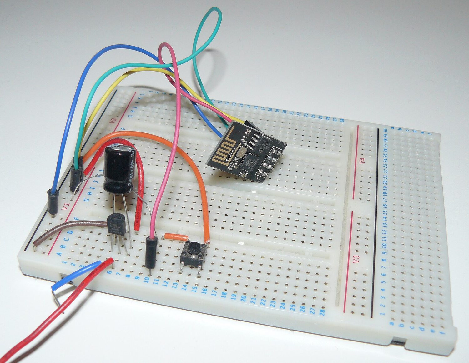
วงจรอิเล็กทรอนิกส์ที่สร้างบนบอร์ดทดลอง
วงจรจริง: ส่วนประกอบเสียบเข้ากับบอร์ดทดลองและเชื่อมต่อด้วยสายเพื่อให้กระแสมีเส้นทางสมบูรณ์
Explore · ⁨สำรวจ⁩

Build series and parallel circuits · ⁨สร้างวงจรแบบอนุกรมและขนาน⁩

In series the same current flows through every bulb and voltage divides; in parallel each branch gets the full voltage. Switch mode to see the bulbs' brightness change. · ⁨ใน แบบอนุกรม กระแสไฟเท่ากันไหลผ่านหลอดไฟทุกดวงและแรงดันไฟฟ้าแบ่งกัน; ใน แบบขนาน แต่ละสาขาได้รับแรงดันไฟฟ้าเต็ม สลับโหมดเพื่อดูความสว่างของหลอดไฟเปลี่ยนไป⁩

Vocabulary · ⁨คำศัพท์⁩ Train · ⁨ฝึกฝน⁩
English ไทย
Electric current/ɪˈlektrɪk ˈkʌrənt/ กระแสไฟฟ้า
amperes/ˈæmpeəz/ แอมแปร์ (amperes)
series/ˈsɪəriːz/ 串联电路中
parallel/ˈpærəlel/ 并联电路中
11.3

Resistance, Resistivity, and Ohm's Law · ⁨ความต้านทาน, ความต้านทานจำเพาะ, และกฎของโอห์ม⁩

Syllabus · ⁨หลักสูตร⁩
English

Learning Objective 11.3.A: Describe the resistance of an object using physical properties of that object.

  • 11.3.A.1 Resistance is a measure of the degree to which an object opposes the movement of electric charge.
  • 11.3.A.2 The resistance of a resistor with uniform geometry is proportional to its resistivity and length and is inversely proportional to its cross-sectional area.
    • Equation: $R = \dfrac{\rho \ell}{A}$
    • 11.3.A.2.i Resistivity is a fundamental property of a material that depends on its atomic and molecular structure and quantifies how strongly the material opposes the motion of electric charge.
    • 11.3.A.2.ii The resistivity of a conductor typically increases with temperature.

Learning Objective 11.3.B: Describe the electrical characteristics of elements of a circuit.

  • 11.3.B.1 Ohm's law relates current, resistance, and potential difference across a conductive element of a circuit.
    • Equation: $I = \dfrac{\Delta V}{R}$
    • 11.3.B.1.i Materials that obey Ohm's law have constant resistance for all currents and are called ohmic materials.
    • 11.3.B.1.ii The resistivity of an ohmic material is constant regardless of temperature.
    • 11.3.B.1.iii Resistors can also convert electrical energy to thermal energy, which may change the temperature of both the resistor and the resistor's environment.
    • 11.3.B.1.iv The resistance of an ohmic circuit element can be determined from the slope of a graph of the current in the element as a function of the potential difference across the element.
ไทย

จุดประสงค์การเรียนรู้ 11.3.A: อธิบายความต้านทานของวัตถุโดยใช้คุณสมบัติทางกายภาพของวัตถุนั้น

  • 11.3.A.1 ความต้านทานคือตัวบ่งชี้ถึงระดับที่วัตถุขัดขวางการเคลื่อนที่ของประจุไฟฟ้า
  • 11.3.A.2 ความต้านทานของตัวต้านทานที่มีรูปทรงสม่ำเสมอจะแปรผันตรงกับค่าความต้านทานจำเพาะและความยาวของมัน และแปรผกผันกับพื้นที่หน้าตัดของมัน
    • สมการ: $R = \dfrac{\rho \ell}{A}$
    • 11.3.A.2.i ความต้านทานจำเพาะเป็นคุณสมบัติพื้นฐานของวัสดุที่ขึ้นอยู่กับโครงสร้างอะตอมและโมเลกุลของวัสดุนั้น และวัดระดับที่วัสดุนั้นขัดขวางการเคลื่อนที่ของประจุไฟฟ้า
    • 11.3.A.2.ii ความต้านทานจำเพาะของตัวนำมักเพิ่มขึ้นเมื่ออุณหภูมิสูงขึ้น

จุดประสงค์การเรียนรู้ 11.3.B: อธิบายลักษณะทางไฟฟ้าขององค์ประกอบในวงจร

  • 11.3.B.1 กฎของโอห์มเชื่อมโยงความสัมพันธ์ระหว่างกระแสไฟฟ้า ความต้านทาน และความต่างศักย์ข้ามองค์ประกอบนำไฟฟ้าในวงจร
    • สมการ: $I = \dfrac{\Delta V}{R}$
    • 11.3.B.1.i วัสดุที่ปฏิบัติตามกฎของโอห์มมีความต้านทานคงที่สำหรับทุกกระแสและเรียกว่า วัสดุแบบโอห์มิก
    • 11.3.B.1.ii ความต้านทานจำเพาะของวัสดุแบบโอห์มิกจะคงที่ไม่ว่าอุณหภูมิจะเปลี่ยนแปลงหรือไม่
    • 11.3.B.1.iii ตัวต้านทานยังสามารถแปลงพลังงานไฟฟ้าเป็นพลังงานความร้อนได้ ซึ่งอาจทำให้ทั้งตัวต้านทานและสภาพแวดล้อมรอบตัวมันมีอุณหภูมิเปลี่ยนแปลงไป
    • 11.3.B.1.iv ความต้านทานขององค์ประกอบวงจรแบบโอห์มิกสามารถหาได้จากความชันของกราฟที่แสดงความสัมพันธ์ระหว่างกระแสในองค์ประกอบกับความต่างศักย์ข้ามองค์ประกอบนั้น

Source: College Board AP Course and Exam Description · ⁨แหล่งที่มา: คำอธิบายหลักสูตรและข้อสอบ College Board AP⁩

English

Resistance 电阻 $R$ opposes current, measured in ohms. Ohm's law 欧姆定律 links the three key quantities:

$$V=IR.$$
A component's resistance depends on the material's resistivity 电阻率 $\rho$, its length, and its cross-sectional area: $R=\dfrac{\rho L}{A}$ – longer and thinner means more resistance.

Worked example. A $2.0\ \text{A}$ current flows through a $6.0\ \Omega$ resistor. The voltage across it is $V=IR=2.0\times6.0=12\ \text{V}$.

ไทย

ความต้านทาน $R$ ต้านทานกระแส, วัดเป็นโอห์ม. กฎของโอห์ม เชื่อมโยงสามปริมาณหลัก:

$$V=IR.$$
ความต้านทานของส่วนประกอบขึ้นอยู่กับ ค่าความต้านทาน $\rho$ ของวัสดุ ความยาว และพื้นที่หน้าตัด: $R=\dfrac{\rho L}{A}$ – ยาวและบาง越多意味着更多的 resistance。

เส้น I-V ของตัวนำตามกฎของโอห์มเป็นเส้นตรงผ่านจุดกำเนิด

ตัวอย่างวิธีทำ. กระแส $2.0\ \text{A}$ ไหลผ่านตัวต้านทาน $6.0\ \Omega$. แรงดันข้ามมันคือ $V=IR=2.0\times6.0=12\ \text{V}$.

Explore · ⁨สำรวจ⁩

Apply Ohm's law · ⁨ใช้กฎของโอห์ม⁩

Ohm's law $V=IR$: for a fixed resistance, current is proportional to voltage. Raise the resistance and the same voltage pushes less current. · ⁨กฎของโอห์ม $V=IR$: สำหรับความต้านทานคงที่ กระแสไฟแปรผันตรงกับแรงดันไฟฟ้า เพิ่มความต้านทานแล้วแรงดันไฟฟ้าเท่าเดิมจะดันกระแสไฟได้น้อยลง⁩

Vocabulary · ⁨คำศัพท์⁩ Train · ⁨ฝึกฝน⁩
English ไทย
Resistance/rɪˈzɪstəns/ การต่อต้าน
Ohm's law/əʊmz lɔː/ กฎของโอห์ม
resistivity/ˌriːzɪˈstɪvəti/ ความต้านทานจำเพาะ
Electric power/ɪˈlektrɪk ˈpaʊə/ กำลังไฟฟ้า
light bulb/laɪt bʌlb/ หลอดไฟ
brightness/ˈbraɪtnəs/ ความสว่าง
equivalent resistance/ɪˈkwɪvələnt rɪˈzɪstəns/ ความต้านทานเทียบเท่า
ammeter/ˈæmiːtə/ แอมมิเตอร์
voltmeter/ˈvəʊltmiːtə/ โวลต์มิเตอร์
nonideal/ˌnɒnaɪˈdɪəl/ ที่ไม่ใช่ในอุดมคติ
Kirchhoff's loop rule/ˈkɜːkhɒfs luːp ruːl/ กฎวงจรของเคิร์ชโฮฟฟ์
Kirchhoff's junction rule/ˈkɜːkhɒfs ˈdʒʌŋkʃn ruːl/ กฎโหนดของเคิร์ชโฮฟฟ์
RC circuit/ˌɑː ˈsiː ˈsɜːkɪt/ วงจร RC
11.4

Electric Power · ⁨กำลังไฟฟ้า⁩

Syllabus · ⁨หลักสูตร⁩
English

Learning Objective 11.4.A: Describe the transfer of energy into, out of, or within an electric circuit, in terms of power.

  • 11.4.A.1 The rate at which energy is transferred, converted, or dissipated by a circuit element depends on the current in the element and the electric potential difference across it.
    • Equation: $P = I \Delta V$
    • Equation (derived): $P = I^2 R = \dfrac{(\Delta V)^2}{R}$
  • 11.4.A.2 The brightness of a bulb increases with power, so power can be used to qualitatively predict the brightness of bulbs in a circuit.
ไทย

จุดประสงค์การเรียนรู้ 11.4.A: อธิบายการถ่ายโอนพลังงานเข้าสู่ ออก หรือภายในวงจรไฟฟ้า โดยใช้หน่วยกำลังไฟฟ้า

  • 11.4.A.1 อัตราที่พลังงานถูกถ่ายโอน แปลงสภาพ หรือสูญเสียโดยองค์ประกอบวงจรขึ้นอยู่กับกระแสไฟฟ้าในองค์ประกอบและความต่างศักย์ไฟฟ้าข้ามองค์ประกอบนั้น
    • สมการ: $P = I \Delta V$
    • สมการ (ที่หาได้): $P = I^2 R = \dfrac{(\Delta V)^2}{R}$
  • 11.4.A.2 ความสว่างของหลอดไฟเพิ่มขึ้นตามกำลังไฟฟ้า ดังนั้นจึงสามารถใช้กำลังไฟฟ้าเพื่อทำนายความสว่างของหลอดไฟในวงจรได้อย่างเชิงคุณภาพ

Source: College Board AP Course and Exam Description · ⁨แหล่งที่มา: คำอธิบายหลักสูตรและข้อสอบ College Board AP⁩

English

Electric power 电功率 is the rate a component converts electrical energy (to heat, light, motion):

$$P=IV=I^2R=\frac{V^2}{R}.$$
Pick the form that uses the quantities you know. A resistor's power all becomes heat.

Worked example. The $6.0\ \Omega$ resistor above, carrying $2.0\ \text{A}$, dissipates $P=I^2R=2.0^2\times6.0=24\ \text{W}$ – equivalently $P=IV=2.0\times12=24\ \text{W}$.

A light bulb 灯泡 is just a resistor that glows, and its brightness 亮度 rises with the power it dissipates. So to rank bulbs, compare their power. In a series string every bulb carries the same current, so by $P=I^2R$ the bulb with the largest resistance is brightest; wired in parallel every bulb gets the full battery voltage, so by $P=V^2/R$ the bulb with the smallest resistance is brightest.

ไทย

กำลังไฟฟ้า คืออัตราที่ส่วนประกอบแปลงพลังงานไฟฟ้า (เป็นความร้อน, แสง, การเคลื่อนที่):

$$P=IV=I^2R=\frac{V^2}{R}.$$
เลือกรูปแบบที่ใช้ปริมาณที่คุณทราบ กำลังของตัวต้านทานทั้งหมดจะกลายเป็นความร้อน

ตัวอย่างวิธีทำ. ตัวต้านทาน $6.0\ \Omega$ ข้างต้น, ที่รับ $2.0\ \text{A}$, กระจาย $P=I^2R=2.0^2\times6.0=24\ \text{W}$ – เทียบเท่ากับ $P=IV=2.0\times12=24\ \text{W}$.

หลอดไฟ ก็คือตัวต้านทานที่เรืองแสง, และ ความสว่าง ของมันเพิ่มขึ้นตาม กำลัง ที่มันกระจาย. ดังนั้นเพื่อจัดลำดับหลอดไฟ ให้เปรียบเทียบกำลัง它们在它们串联电路中每个灯泡承载相同的电流,因此根据 $P=I^2R$,电阻最大的灯泡最亮;并联时每个灯泡获得完整的电池电压,因此根据 $P=V^2/R$,电阻最小的灯泡最亮。

สายส่งไฟฟ้าแรงสูง: กำลังไฟฟ้าส่งผ่านแรงดันสูงเพื่อให้กระแส (และความสูญเสีย I²R) ต่ำ
Explore · ⁨สำรวจ⁩

Read an I-V characteristic · ⁨อ่านกราฟลักษณะ I-V⁩

Power is $P=IV$. A resistor's I-V line is straight, but a lamp curves as it heats and its resistance rises. The area under I-V relates to the energy delivered. · ⁨กำลังคือ $P=IV$. กราฟ I-V ของตัวต้านทานเป็นเส้นตรง แต่ โคมไฟ มีเส้นโค้งเมื่อร้อนขึ้นและความต้านทานเพิ่มขึ้น พื้นที่ใต้กราฟ I-Vสัมพันธ์กับพลังงานที่ส่งมอบ⁩

11.5

Compound DC Circuits · ⁨วงจร DC แบบผสม⁩

Syllabus · ⁨หลักสูตร⁩
English

Learning Objective 11.5.A: Describe the equivalent resistance of multiple resistors connected in a circuit.

  • 11.5.A.1 Circuit elements may be connected in series and/or in parallel.
    • 11.5.A.1.i A series connection is one in which any charge passing through one circuit element must proceed through all elements in that connection and has no other path available. The current in each element in series must be the same.
    • 11.5.A.1.ii A parallel connection is one in which charges may flow through one of two or more paths. Across each path, the potential difference is the same.
  • 11.5.A.2 A collection of resistors in a circuit may be analyzed as though it were a single resistor with an equivalent resistance $R_{\text{eq}}$.
    • 11.5.A.2.i The equivalent resistance of a set of resistors in series is the sum of the individual resistances.
      • Equation: $R_{\text{eq},s} = \sum_i R_i$
    • 11.5.A.2.ii The inverse of the equivalent resistance of a set of resistors connected in parallel is equal to the sum of the inverses of the individual resistances.
      • Equation: $\dfrac{1}{R_{\text{eq},p}} = \sum_i \dfrac{1}{R_i}$
    • 11.5.A.2.iii When resistors are connected in parallel, the number of paths available to charges increases, and the equivalent resistance of the group of resistors decreases.

Learning Objective 11.5.B: Describe a circuit with resistive wires and a battery with internal resistance.

  • 11.5.B.1 Ideal batteries have negligible internal resistance. Ideal wires have negligible resistance.
    • 11.5.B.1.i The resistance of wires that are good conductors may normally be neglected, because their resistance is much smaller than that of other elements of a circuit.
    • 11.5.B.1.ii The resistance of wires may only be neglected if the circuit contains other elements that do have resistance.
    • 11.5.B.1.iii The potential difference a battery would supply if it were ideal is the potential difference measured across the terminals when there is no current in the battery and is sometimes referred to as its $\mathrm{emf}$ ($\varepsilon$).
  • 11.5.B.2 The internal resistance of a nonideal battery may be treated as the resistance of a resistor in series with an ideal battery and the remainder of the circuit.
  • 11.5.B.3 When there is current in a nonideal battery with internal resistance $r$, the potential difference across the terminals of the battery is reduced relative to the potential difference when there is no current in the battery.
    • Equation (derived): $\Delta V_{\text{terminal}} = \varepsilon - Ir$

Learning Objective 11.5.C: Describe the measurement of current and potential difference in a circuit.

  • 11.5.C.1 Ammeters are used to measure current at a specific point in a circuit.
    • 11.5.C.1.i Ammeters must be connected in series with the element in which current is being measured.
    • 11.5.C.1.ii Ideal ammeters have zero resistance so that they do not affect the current in the element that they are in series with.
  • 11.5.C.2 Voltmeters are used to measure electric potential difference between two points in a circuit.
    • 11.5.C.2.i Voltmeters must be connected in parallel with the element across which potential difference is being measured.
    • 11.5.C.2.ii Ideal voltmeters have an infinite resistance so that no charge flows through them.
  • 11.5.C.3 Nonideal ammeters and voltmeters will change the properties of the circuit being measured.

Boundary statement: AP Physics 2 only expects students to qualitatively discuss how a nonideal ammeter or voltmeter will affect the results of measurements. Unless otherwise stated, all batteries, wires, and meters are assumed to be ideal.

Boundary statement: Circuits with batteries of different potential differences connected in parallel will not be assessed.

ไทย

จุดประสงค์การเรียนรู้ 11.5.A: อธิบายความต้านทานเทียบเท่าของตัวต้านทานหลายตัวที่ต่ออยู่ในวงจร

  • 11.5.A.1 องค์ประกอบวงจรอาจต่อกันแบบอนุกรมและ/หรือแบบขนาน
    • 11.5.A.1.i การต่อแบบอนุกรมคือการเชื่อมต่อที่ประจุใดๆ ที่ไหลผ่านองค์ประกอบวงจรหนึ่งจะต้องไหลผ่านองค์ประกอบทั้งหมดในการต่อนั้นและไม่ไม่มีเส้นทางอื่นให้เลือก กระแสไฟฟ้าในแต่ละองค์ประกอบที่ต่อกันแบบอนุกรมต้องมีค่าเท่ากัน
    • 11.5.A.1.ii การต่อแบบขนานคือการที่ประจุสามารถไหลผ่านเส้นทางใดเส้นทางหนึ่งจากสองหรือมากกว่า这条路 Across each path, the potential difference is the same.
  • 11.5.A.2 ชุดตัวต้านทานในวงจรอาจวิเคราะห์เสมือนว่าเป็นตัวต้านทานเดี่ยวที่มีค่าความต้านทานสมมูล $R_{\text{eq}}$
    • 11.5.A.2.i ความต้านทานสมมูลของชุดตัวต้านทานที่ต่อกันแบบอนุกรมคือผลบวกของความต้านทานแต่ละตัว
      • สมการ: $R_{\text{eq},s} = \sum_i R_i$
    • 11.5.A.2.ii ค่าผกผันของความต้านทานสมมูลของชุดตัวต้านทานที่ต่อกันแบบขนานเท่ากับผลบวกของค่าผกผันของความต้านทานแต่ละตัว
      • สมการ: $\dfrac{1}{R_{\text{eq},p}} = \sum_i \dfrac{1}{R_i}$
    • 11.5.A.2.iii เมื่อตัวต้านทานต่อแบบขนาน จำนวนเส้นทางที่ประจุไฟฟ้าสามารถไหลผ่านจะเพิ่มขึ้น และค่าความต้านทานเทียบเท่าของชุดตัวต้านทานจะลดลง

วัตถุประสงค์การเรียนรู้ 11.5.B: อธิบายวงจรที่มีสายไฟที่มีความต้านทานและแบตเตอรี่ที่มีความต้านทานภายใน

  • 11.5.B.1 แบตเตอรี่ในอุดมคติมีความต้านทานภายในน้อยมากจนละเลยได้ สายไฟในอุดมียก็มีความต้านทานต่ำมากจนละเลยได้
    • 11.5.B.1.i ความต้านทานของสายไฟที่เป็นตัวนำที่ดีมักถูกมองข้ามได้ เนื่องจากมีความต้านทานน้อยกว่าองค์ประกอบอื่นๆ ในวงจรอย่างมาก
    • 11.5.B.1.ii สามารถมองข้ามความต้านทานของสายไฟได้ก็ต่อเมื่อวงจรมีองค์ประกอบอื่นที่มีค่าความต้านทานอยู่ด้วย
    • 11.5.B.1.iii แรงดันไฟฟ้าที่แบตเตอรี่จะจ่ายออกมาหากเป็นแบตเตอรี่ในอุดมคติ คือแรงดันไฟฟ้าที่วัดได้ระหว่างขั้วแบตเตอรี่เมื่อไม่มีกระแสไฟฟ้าไหลผ่าน และบางครั้งเรียกว่า $\mathrm{emf}$ ($\varepsilon$)
  • 11.5.B.2 ความต้านทานภายในของแบตเตอรี่ที่ไม่ใช่ในอุดมียสามารถพิจารณา等效เป็นความต้านทานของตัวต้านทานที่ต่อกับแบตเตอรี่ในอุดมียและส่วนที่เหลือของวงจรแบบอนุกรม
  • 11.5.B.3 เมื่อมีกระแสไหลผ่านแบตเตอรี่ที่ไม่ใช่ในอุดมียที่มีความต้านทานภายใน $r$ ความต่างศักย์ระหว่างขั้วทั้งสองของแบตเตอรี่จะลดลงเมื่อเทียบกับความต่างศักย์เมื่อไม่มีกระแสไหลผ่านแบตเตอรี่
    • สมการ (ที่หาได้): $\Delta V_{\text{terminal}} = \varepsilon - Ir$

วัตถุประสงค์การเรียนรู้ 11.5.C: อธิบายการวัดกระแสและความต่างศักย์ในวงจร

  • 11.5.C.1 อะมมิเตอร์ใช้เพื่อวัดกระแสที่จุดเฉพาะในวงจร
    • 11.5.C.1.i อะมมิเตอร์ต้องต่อแบบอนุกรมกับองค์ประกอบที่ต้องการวัดกระแสไฟฟ้า
    • 11.5.C.1.ii อะมมิเตอร์ในอุดมคติมีความต้านทานเป็นศูนย์เพื่อให้ไม่รบกวนกระแสไฟฟ้าในองค์ประกอบที่ต่อแบบอนุกรมด้วยกัน
  • 11.5.C.2 โวลต์มิเตอร์ใช้เพื่อวัดความต่างศักย์ไฟฟ้าระหว่างสองจุดในวงจร
    • 11.5.C.2.i โวลต์มิเตอร์ต้องต่อแบบขนานกับองค์ประกอบที่ต้องการวัดแรงดันไฟฟ้าตกคร่อม
    • 11.5.C.2.ii โวลต์มิเตอร์ในอุดมคติมีความต้านทานเป็นอนันต์เพื่อไม่ให้มีประจุไฟฟ้าไหลผ่าน
  • 11.5.C.3 อะมมิเตอร์และโวลต์มิเตอร์ที่ไม่ใช่ในอุดมียจะทำให้คุณสมบัติของวงจรที่ต้องการวัดเปลี่ยนแปลงไป

ข้อจำกัด: AP Physics 2 จะ要求学生เพียงการอธิบายเชิงคุณภาพว่าอะมมิเตอร์หรือโวลต์มิเตอร์ที่ไม่ใช่ในอุดมียจะมีผลต่อการวัดอย่างไร เว้นแต่จะระบุไว้เป็นอย่างอื่น แบตเตอรี่ สายไฟ และเครื่องวัดทั้งหมดถูกสมมติให้เป็นในอุดมีย

ข้อจำกัด: วงจรที่มีแบตเตอรี่ที่มีความต่างศักย์ต่างกันต่อกันแบบขนานจะไม่ถูกประเมิน

Source: College Board AP Course and Exam Description · ⁨แหล่งที่มา: คำอธิบายหลักสูตรและข้อสอบ College Board AP⁩

English

Combine resistors to find an equivalent resistance 等效电阻:

  • Series: $R_{\text{eq}}=R_1+R_2+\cdots$ (resistances add).
  • Parallel: $\dfrac{1}{R_{\text{eq}}}=\dfrac{1}{R_1}+\dfrac{1}{R_2}+\cdots$ (the total is less than the smallest).

Reduce the network step by step to find the total current from the battery, then work back to each element.

Worked example. A $12\ \text{V}$ battery drives a $4.0\ \Omega$ and a $12\ \Omega$ resistor in parallel. First combine them: $\dfrac{1}{R_{\text{eq}}}=\dfrac14+\dfrac{1}{12}=\dfrac{4}{12}\Rightarrow R_{\text{eq}}=3.0\ \Omega$. The total current from the battery is $I=\dfrac{V}{R_{\text{eq}}}=\dfrac{12}{3.0}=4.0\ \text{A}$, which splits so that the smaller resistor carries the larger share ($3.0\ \text{A}$ through the $4\ \Omega$, $1.0\ \text{A}$ through the $12\ \Omega$).

ไทย

รวมตัวต้านทานเพื่อหา ความต้านทานเทียบเท่า:

ตัวต้านทานต่อแบบอนุกรมรวมเป็นความต้านทานสมมูลเดียว
  • แบบอนุกรม: $R_{\text{eq}}=R_1+R_2+\cdots$ (ความต้านทานบวกกัน).
  • แบบขนาน: $\dfrac{1}{R_{\text{eq}}}=\dfrac{1}{R_1}+\dfrac{1}{R_2}+\cdots$ (ค่ารวมมีค่าน้อยกว่าค่าที่น้อยที่สุด).

ลดวงจรทีละขั้นเพื่อหาค่ากระแสรวมจากแบตเตอรี่ แล้วคำนวณย้อนกลับไปยังองค์ประกอบแต่ละตัว

ตัวอย่างการคำนวณ. แบตเตอรี่ $12\ \text{V}$ ขับเคลื่อนตัวต้านทาน $4.0\ \Omega$ และ $12\ \Omega$ ต่อแบบ ขนาน. รวมค่าเข้าด้วยกัน: $\dfrac{1}{R_{\text{eq}}}=\dfrac14+\dfrac{1}{12}=\dfrac{4}{12}\Rightarrow R_{\text{eq}}=3.0\ \Omega$. กระแสรวมจากแบตเตอรี่คือ $I=\dfrac{V}{R_{\text{eq}}}=\dfrac{12}{3.0}=4.0\ \text{A}$ ซึ่งจะแยกไป так ที่ตัวต้านทานที่มีค่าน้อยจะรับกระแสส่วนมาก ($3.0\ \text{A}$ ผ่าน $4\ \Omega$, $1.0\ \text{A}$ ผ่าน $12\ \Omega$).

11.5

Measuring Current and Voltage · ⁨การวัดกระแสและแรงดันไฟฟ้า⁩

Syllabus · ⁨หลักสูตร⁩
English

Learning Objective 11.5.A: Describe the equivalent resistance of multiple resistors connected in a circuit.

  • 11.5.A.1 Circuit elements may be connected in series and/or in parallel.
    • 11.5.A.1.i A series connection is one in which any charge passing through one circuit element must proceed through all elements in that connection and has no other path available. The current in each element in series must be the same.
    • 11.5.A.1.ii A parallel connection is one in which charges may flow through one of two or more paths. Across each path, the potential difference is the same.
  • 11.5.A.2 A collection of resistors in a circuit may be analyzed as though it were a single resistor with an equivalent resistance $R_{\text{eq}}$.
    • 11.5.A.2.i The equivalent resistance of a set of resistors in series is the sum of the individual resistances.
      • Equation: $R_{\text{eq},s} = \sum_i R_i$
    • 11.5.A.2.ii The inverse of the equivalent resistance of a set of resistors connected in parallel is equal to the sum of the inverses of the individual resistances.
      • Equation: $\dfrac{1}{R_{\text{eq},p}} = \sum_i \dfrac{1}{R_i}$
    • 11.5.A.2.iii When resistors are connected in parallel, the number of paths available to charges increases, and the equivalent resistance of the group of resistors decreases.

Learning Objective 11.5.B: Describe a circuit with resistive wires and a battery with internal resistance.

  • 11.5.B.1 Ideal batteries have negligible internal resistance. Ideal wires have negligible resistance.
    • 11.5.B.1.i The resistance of wires that are good conductors may normally be neglected, because their resistance is much smaller than that of other elements of a circuit.
    • 11.5.B.1.ii The resistance of wires may only be neglected if the circuit contains other elements that do have resistance.
    • 11.5.B.1.iii The potential difference a battery would supply if it were ideal is the potential difference measured across the terminals when there is no current in the battery and is sometimes referred to as its $\mathrm{emf}$ ($\varepsilon$).
  • 11.5.B.2 The internal resistance of a nonideal battery may be treated as the resistance of a resistor in series with an ideal battery and the remainder of the circuit.
  • 11.5.B.3 When there is current in a nonideal battery with internal resistance $r$, the potential difference across the terminals of the battery is reduced relative to the potential difference when there is no current in the battery.
    • Equation (derived): $\Delta V_{\text{terminal}} = \varepsilon - Ir$

Learning Objective 11.5.C: Describe the measurement of current and potential difference in a circuit.

  • 11.5.C.1 Ammeters are used to measure current at a specific point in a circuit.
    • 11.5.C.1.i Ammeters must be connected in series with the element in which current is being measured.
    • 11.5.C.1.ii Ideal ammeters have zero resistance so that they do not affect the current in the element that they are in series with.
  • 11.5.C.2 Voltmeters are used to measure electric potential difference between two points in a circuit.
    • 11.5.C.2.i Voltmeters must be connected in parallel with the element across which potential difference is being measured.
    • 11.5.C.2.ii Ideal voltmeters have an infinite resistance so that no charge flows through them.
  • 11.5.C.3 Nonideal ammeters and voltmeters will change the properties of the circuit being measured.

Boundary statement: AP Physics 2 only expects students to qualitatively discuss how a nonideal ammeter or voltmeter will affect the results of measurements. Unless otherwise stated, all batteries, wires, and meters are assumed to be ideal.

Boundary statement: Circuits with batteries of different potential differences connected in parallel will not be assessed.

ไทย

จุดประสงค์การเรียนรู้ 11.5.A: อธิบายความต้านทานเทียบเท่าของตัวต้านทานหลายตัวที่ต่ออยู่ในวงจร

  • 11.5.A.1 องค์ประกอบวงจรอาจต่อกันแบบอนุกรมและ/หรือแบบขนาน
    • 11.5.A.1.i การต่อแบบอนุกรมคือการเชื่อมต่อที่ประจุใดๆ ที่ไหลผ่านองค์ประกอบวงจรหนึ่งจะต้องไหลผ่านองค์ประกอบทั้งหมดในการต่อนั้นและไม่ไม่มีเส้นทางอื่นให้เลือก กระแสไฟฟ้าในแต่ละองค์ประกอบที่ต่อกันแบบอนุกรมต้องมีค่าเท่ากัน
    • 11.5.A.1.ii การต่อแบบขนานคือการที่ประจุสามารถไหลผ่านเส้นทางใดเส้นทางหนึ่งจากสองหรือมากกว่า这条路 Across each path, the potential difference is the same.
  • 11.5.A.2 ชุดตัวต้านทานในวงจรอาจวิเคราะห์เสมือนว่าเป็นตัวต้านทานเดี่ยวที่มีค่าความต้านทานสมมูล $R_{\text{eq}}$
    • 11.5.A.2.i ความต้านทานสมมูลของชุดตัวต้านทานที่ต่อกันแบบอนุกรมคือผลบวกของความต้านทานแต่ละตัว
      • สมการ: $R_{\text{eq},s} = \sum_i R_i$
    • 11.5.A.2.ii ค่าผกผันของความต้านทานสมมูลของชุดตัวต้านทานที่ต่อกันแบบขนานเท่ากับผลบวกของค่าผกผันของความต้านทานแต่ละตัว
      • สมการ: $\dfrac{1}{R_{\text{eq},p}} = \sum_i \dfrac{1}{R_i}$
    • 11.5.A.2.iii เมื่อตัวต้านทานต่อแบบขนาน จำนวนเส้นทางที่ประจุไฟฟ้าสามารถไหลผ่านจะเพิ่มขึ้น และค่าความต้านทานเทียบเท่าของชุดตัวต้านทานจะลดลง

วัตถุประสงค์การเรียนรู้ 11.5.B: อธิบายวงจรที่มีสายไฟที่มีความต้านทานและแบตเตอรี่ที่มีความต้านทานภายใน

  • 11.5.B.1 แบตเตอรี่ในอุดมคติมีความต้านทานภายในน้อยมากจนละเลยได้ สายไฟในอุดมียก็มีความต้านทานต่ำมากจนละเลยได้
    • 11.5.B.1.i ความต้านทานของสายไฟที่เป็นตัวนำที่ดีมักถูกมองข้ามได้ เนื่องจากมีความต้านทานน้อยกว่าองค์ประกอบอื่นๆ ในวงจรอย่างมาก
    • 11.5.B.1.ii สามารถมองข้ามความต้านทานของสายไฟได้ก็ต่อเมื่อวงจรมีองค์ประกอบอื่นที่มีค่าความต้านทานอยู่ด้วย
    • 11.5.B.1.iii แรงดันไฟฟ้าที่แบตเตอรี่จะจ่ายออกมาหากเป็นแบตเตอรี่ในอุดมคติ คือแรงดันไฟฟ้าที่วัดได้ระหว่างขั้วแบตเตอรี่เมื่อไม่มีกระแสไฟฟ้าไหลผ่าน และบางครั้งเรียกว่า $\mathrm{emf}$ ($\varepsilon$)
  • 11.5.B.2 ความต้านทานภายในของแบตเตอรี่ที่ไม่ใช่ในอุดมียสามารถพิจารณา等效เป็นความต้านทานของตัวต้านทานที่ต่อกับแบตเตอรี่ในอุดมียและส่วนที่เหลือของวงจรแบบอนุกรม
  • 11.5.B.3 เมื่อมีกระแสไหลผ่านแบตเตอรี่ที่ไม่ใช่ในอุดมียที่มีความต้านทานภายใน $r$ ความต่างศักย์ระหว่างขั้วทั้งสองของแบตเตอรี่จะลดลงเมื่อเทียบกับความต่างศักย์เมื่อไม่มีกระแสไหลผ่านแบตเตอรี่
    • สมการ (ที่หาได้): $\Delta V_{\text{terminal}} = \varepsilon - Ir$

วัตถุประสงค์การเรียนรู้ 11.5.C: อธิบายการวัดกระแสและความต่างศักย์ในวงจร

  • 11.5.C.1 อะมมิเตอร์ใช้เพื่อวัดกระแสที่จุดเฉพาะในวงจร
    • 11.5.C.1.i อะมมิเตอร์ต้องต่อแบบอนุกรมกับองค์ประกอบที่ต้องการวัดกระแสไฟฟ้า
    • 11.5.C.1.ii อะมมิเตอร์ในอุดมคติมีความต้านทานเป็นศูนย์เพื่อให้ไม่รบกวนกระแสไฟฟ้าในองค์ประกอบที่ต่อแบบอนุกรมด้วยกัน
  • 11.5.C.2 โวลต์มิเตอร์ใช้เพื่อวัดความต่างศักย์ไฟฟ้าระหว่างสองจุดในวงจร
    • 11.5.C.2.i โวลต์มิเตอร์ต้องต่อแบบขนานกับองค์ประกอบที่ต้องการวัดแรงดันไฟฟ้าตกคร่อม
    • 11.5.C.2.ii โวลต์มิเตอร์ในอุดมคติมีความต้านทานเป็นอนันต์เพื่อไม่ให้มีประจุไฟฟ้าไหลผ่าน
  • 11.5.C.3 อะมมิเตอร์และโวลต์มิเตอร์ที่ไม่ใช่ในอุดมียจะทำให้คุณสมบัติของวงจรที่ต้องการวัดเปลี่ยนแปลงไป

ข้อจำกัด: AP Physics 2 จะ要求学生เพียงการอธิบายเชิงคุณภาพว่าอะมมิเตอร์หรือโวลต์มิเตอร์ที่ไม่ใช่ในอุดมียจะมีผลต่อการวัดอย่างไร เว้นแต่จะระบุไว้เป็นอย่างอื่น แบตเตอรี่ สายไฟ และเครื่องวัดทั้งหมดถูกสมมติให้เป็นในอุดมีย

ข้อจำกัด: วงจรที่มีแบตเตอรี่ที่มีความต่างศักย์ต่างกันต่อกันแบบขนานจะไม่ถูกประเมิน

Source: College Board AP Course and Exam Description · ⁨แหล่งที่มา: คำอธิบายหลักสูตรและข้อสอบ College Board AP⁩

English

Two meters read a circuit. An ammeter 电流表 measures the current at a point, so it must be wired in series – the current you want to measure has to flow through it. A voltmeter 电压表 measures the potential difference between two points, so it is wired in parallel, bridging across the component whose voltage you want.

For a meter to read the true value it must barely disturb the circuit:

  • an ideal ammeter has zero resistance, so putting it in series does not reduce the current it reads;
  • an ideal voltmeter has infinite resistance, so almost no current is diverted through it.

A real, nonideal 非理想 meter is imperfect: a real ammeter has a small resistance (it slightly lowers the current), and a real voltmeter lets a little current leak through (it slightly lowers the voltage it reads). So connecting any meter changes, a little, the very quantity it is measuring.

ไทย

เครื่องวัดสองชนิดอ่านค่าวงจร. แอมมิเตอร์ วัดกระแส ณ จุดหนึ่ง จึงต้องต่อแบบ อนุกรม – กระแสที่ต้องการวัดต้องไหล ผ่าน ตัวมัน. โวลต์มิเตอร์ วัดผลต่างศักย์ระหว่างสองจุด จึงต่อแบบ ขนาน ข้ามข้ามองค์ประกอบ whose voltage คุณต้องการวัด.

เพื่อให้เครื่องวัดอ่านค่าจริงได้ มันต้องรบกวนวงจรน้อยที่สุด:

  • แอมมิเตอร์ในอุดมคติ มี ความต้านทานเป็นศูนย์, การต่อแบบอนุกรมจึงไม่ทำให้กระแสที่อ่านได้น้อยลง;
  • โวลต์มิเตอร์ในอุดมคติ มี ความต้านทานเป็นอนันต์, กระแสแทบจะไม่เบี่ยงเบนไหลผ่านมันเลย.

เครื่องวัดจริงที่ไม่ใช่อุดมคติมีความไม่สมบูรณ์แบบ: แอมมิเตอร์จริงมีความต้านทานเล็กน้อย (ลดกระแสลงเล็กน้อย), และโวลต์มิเตอร์จริงให้กระแสรั่วไหลผ่านบ้าง (ลดแรงดันที่อ่านได้น้อยลง). ดังนั้น การเชื่อมต่อเครื่องวัดใดๆ ก็ตาม จะเปลี่ยนแปลงปริมาณที่มันกำลังวัดไปเพียงเล็กน้อยเท่านั้น

11.6

Kirchhoff's Loop Rule · ⁨กฎวงจรรอบของเคอร์ชอฟฟ์⁩

Syllabus · ⁨หลักสูตร⁩
English

Learning Objective 11.6.A: Describe a circuit or elements of a circuit by applying Kirchhoff's loop rule.

  • 11.6.A.1 Energy changes in simple electrical circuits may be represented in terms of charges moving through electric potential differences within circuit elements.
    • Equation: $\Delta U_E = q \Delta V$
  • 11.6.A.2 Kirchhoff's loop rule is a consequence of the conservation of energy.
  • 11.6.A.3 Kirchhoff's loop rule states that the sum of potential differences across all circuit elements in a single closed loop must equal zero.
    • Equation: $\sum \Delta V = 0$
  • 11.6.A.4 The values of electric potential at points in a circuit can be represented by a graph of electric potential as a function of position within a loop.
ไทย

วัตถุประสงค์การเรียนรู้ 11.6.A: อธิบายวงจรหรือองค์ประกอบของวงจรโดยใช้กฎลูปของคีร์ชฮอฟฟ์

  • 11.6.A.1 การเปลี่ยนแปลงพลังงานในวงจรรวมไฟฟ้าอย่างง่ายสามารถแสดงได้ในรูปของประจุที่เคลื่อนที่ผ่านความต่างศักย์ไฟฟ้าภายในองค์ประกอบของวงจร
    • สมการ: $\Delta U_E = q \Delta V$
  • 11.6.A.2 กฎลูปของคีร์ชฮอฟฟ์เป็นผลมาจากการอนุรักษ์พลังงาน
  • 11.6.A.3 กฎลูปของคีร์ชฮอฟฟ์ระบุว่าผลรวมของความต่างศักย์ตลอดองค์ประกอบทั้งหมดในลูปปิดเดียวต้องเท่ากับศูนย์
    • สมการ: $\sum \Delta V = 0$
  • 11.6.A.4 ค่าความต่างศักย์ไฟฟ้าที่จุดต่างๆ ในวงจรสามารถแสดงได้ด้วยกราฟของความต่างศักย์ไฟฟ้าในฟังก์ชันของตำแหน่งภายในลูป

Source: College Board AP Course and Exam Description · ⁨แหล่งที่มา: คำอธิบายหลักสูตรและข้อสอบ College Board AP⁩

English

Kirchhoff's loop rule 基尔霍夫电压定律 (energy conservation): around any closed loop, the voltage gains and drops sum to zero. Add the battery's emf and subtract each $IR$ drop as you go around. This gives one equation per independent loop.

ไทย

กฎวงจรรอบของเคอร์ชอฟฟ์ (การอนุรักษ์พลังงาน): รอบวงจรรูปปิดใดๆ ผลรวมของการเพิ่มและลดลงของแรงดันไฟฟ้าจะเป็น ศูนย์. บวก emf ของแบตเตอรี่และลบการลดลงของ $IR$ แต่ละค่าเมื่อวนรอบ. สิ่งนี้ให้สมการหนึ่งสมการต่อวงจรรูปอิสระหนึ่งรูป

11.7

Kirchhoff's Junction Rule · ⁨กฎจุดต่อของเคอร์ชอฟฟ์⁩

Syllabus · ⁨หลักสูตร⁩
English

Learning Objective 11.7.A: Describe a circuit or elements of a circuit by applying Kirchhoff's junction rule.

  • 11.7.A.1 Kirchhoff's junction rule is a consequence of the conservation of electric charge.
  • 11.7.A.2 Kirchhoff's junction rule states that the total amount of charge entering a junction per unit time must equal the total amount of charge exiting that junction per unit time.
    • Equation: $\sum I_{\text{in}} = \sum I_{\text{out}}$
ไทย

วัตถุประสงค์การเรียนรู้ 11.7.A: อธิบายวงจรหรือองค์ประกอบของวงจรโดยใช้กฎจุดต่อของคีร์ชฮอฟฟ์

  • 11.7.A.1 กฎจุดต่อของคีร์ชฮอฟฟ์เป็นผลมาจากการอนุรักษ์ประจุไฟฟ้า
  • 11.7.A.2 กฎจุดต่อของคีร์ชฮอฟฟ์ระบุว่าปริมาณประจุทั้งหมดที่เข้าสู่จุดต่อต่อหน่วยเวลาต้องเท่ากับปริมาณประจุทั้งหมดที่ออกจากจุดต่อนั้นต่อหน่วยเวลา
    • สมการ: $\sum I_{\text{in}} = \sum I_{\text{out}}$

Source: College Board AP Course and Exam Description · ⁨แหล่งที่มา: คำอธิบายหลักสูตรและข้อสอบ College Board AP⁩

English

Kirchhoff's junction rule 基尔霍夫电流定律 (charge conservation): the total current into any junction equals the total current out. Together with the loop rule, it lets you solve any multi-loop circuit for its unknown currents.

ไทย

กฎจุดต่อของเคอร์ชอฟฟ์ (การอนุรักษ์ประจุ): กระแสรวมที่ เข้าสู่ จุดต่อใดจุดหนึ่งเท่ากับกระแสรวมที่ ออก. ร่วมกับกฎวงจรรอบ ทำให้คุณสามารถแก้วงจรหลายวงจรรูปเพื่อหาค่ากระแสที่ไม่ทราบค่าได้

กระแสแยกที่จุดต่อ:สิ่งที่ไหลเข้าเท่ากับสิ่งที่ไหลออก
11.8

RC Circuits · ⁨วงจร RC⁩

Syllabus · ⁨หลักสูตร⁩
English

Learning Objective 11.8.A: Describe the equivalent capacitance of multiple capacitors.

  • 11.8.A.1 A collection of capacitors in a circuit may be analyzed as though it were a single capacitor with an equivalent capacitance $C_{\text{eq}}$.
    • 11.8.A.1.i The inverse of the equivalent capacitance of a set of capacitors connected in series is equal to the sum of the inverses of the individual capacitances.
      • Equation: $\dfrac{1}{C_{\text{eq},s}} = \sum_i \dfrac{1}{C_i}$
    • 11.8.A.1.ii The equivalent capacitance of a set of capacitors in series is less than the capacitance of the smallest capacitor.
    • 11.8.A.1.iii The equivalent capacitance of a set of capacitors in parallel is the sum of the individual capacitances.
      • Equation: $C_{\text{eq},p} = \sum_i C_i$
  • 11.8.A.2 As a result of conservation of charge, each of the capacitors in series must have the same magnitude of charge on each plate.

Learning Objective 11.8.B: Describe the behavior of a circuit containing combinations of resistors and capacitors.

  • 11.8.B.1 The time constant $\tau$ is a significant feature of an RC circuit.
    • 11.8.B.1.i The time constant of an RC circuit is a measure of how quickly the capacitor will charge or discharge and is defined as $\tau = R_{\text{eq}} C_{\text{eq}}$.
    • 11.8.B.1.ii For a charging capacitor, the time constant represents the time required for the capacitor's charge to increase from zero to approximately 63 percent of its final asymptotic value.
    • 11.8.B.1.iii For a discharging capacitor, the time constant represents the time required for the capacitor's charge to decrease from fully charged to approximately 37 percent of its initial value.
  • 11.8.B.2 The potential difference across a capacitor and the current in the branch of the circuit containing the capacitor each change over time as the capacitor charges and discharges, but both will reach a steady state after a long time interval.
    • 11.8.B.2.i Immediately after being placed in a circuit, an uncharged capacitor acts like a wire, and charge can easily flow to or from the plates of the capacitor.
    • 11.8.B.2.ii As a capacitor charges, changes to the potential difference across the capacitor affect the charge on the plates of the capacitor, the current circuit branch in which the capacitor is located, and the electric potential energy stored in the capacitor.
    • 11.8.B.2.iii The potential difference across a capacitor, the current in the circuit branch in which the capacitor is located, and the electric potential energy stored in the capacitor all change with respect to time and asymptotically approach steady state conditions.
    • 11.8.B.2.iv After a long time, a charging capacitor approaches a state of being fully charged, reaching a maximum potential difference at which there is zero current in the circuit branch in which the capacitor is located.
    • 11.8.B.2.v Immediately after a charged capacitor begins discharging, the amount of charge on the capacitor plates and the energy stored in the capacitor begin to decrease.
    • 11.8.B.2.vi As a capacitor discharges, the amount of charge on the capacitor, the potential difference across the capacitor, and the current in the circuit branch in which the capacitor is located all decrease until a steady state is reached.
    • 11.8.B.2.vii After either charging or discharging for times much greater than the time constant, the capacitor and the relevant circuit branch may be modeled using steady-state conditions.

Boundary statement: Descriptions of charging/discharging RC circuits in AP Physics 2 are limited to qualitative descriptions and representations. While students should be able to mathematically describe initial and final states of RC circuits, students are not expected to mathematically model these behaviors with respect to time.

ไทย

วัตถุประสงค์การเรียนรู้ 11.8.A: อธิบายความจุสมมูลของตัวเก็บประจุหลายตัว

  • 11.8.A.1 ชุดตัวเก็บประจุในวงจรอาจวิเคราะห์เสมือนว่าเป็นตัวเก็บประจุเดี่ยวที่มีความจุสมมูล $C_{\text{eq}}$
    • 11.8.A.1.i ส่วนกลับของความจุเทียบเท่าของชุดตัวเก็บประจุที่ต่อแบบอนุกรม มีค่าเท่ากับผลรวมของส่วนกลับของความจุของแต่ละตัว
      • สมการ: $\dfrac{1}{C_{\text{eq},s}} = \sum_i \dfrac{1}{C_i}$
    • 11.8.A.1.ii ค่าความจุเทียบเท่าของชุดตัวเก็บประจุที่ต่อแบบอนุกรม จะมีค่าน้อยกว่าความจุของตัวเก็บประจุที่มีค่าน้อยที่สุด
    • 11.8.A.1.iii ค่าความจุเทียบเท่าของชุดตัวเก็บประจุที่ต่อแบบขนาน เป็นผลรวมของความจุของแต่ละตัว
      • สมการ: $C_{\text{eq},p} = \sum_i C_i$
  • 11.8.A.2 เนื่องจากหลักการอนุรักษ์ประจุ ตัวเก็บประจุแต่ละตัวในชุดที่ต่อกันแบบอนุกรมต้องมีขนาดของประจุเท่ากันบนแผ่นแต่ละแผ่น

วัตถุประสงค์การเรียนรู้ 11.8.B: อธิบายพฤติกรรมของวงจรที่ประกอบด้วยชุดผสมของตัวต้านทานและตัวเก็บประจุ

  • 11.8.B.1 ค่าคงที่เวลา $\tau$ เป็นคุณลักษณะสำคัญของวงจร RC
    • 11.8.B.1.i ค่าคงที่เวลาของ RC วงจรคือตัวชี้วัดความเร็วในการชาร์จหรือการคายประจุของตัวเก็บประจุ และนิยามไว้ว่า $\tau = R_{\text{eq}} C_{\text{eq}}$
    • 11.8.B.1.ii สำหรับตัวเก็บประจุที่กำลังชาร์จ ค่าคงที่เวลาแทนถึงระยะเวลาที่ต้องใช้เพื่อให้ประจุของตัวเก็บประจุเพิ่มขึ้นจากศูนย์ไปประมาณ 63 เปอร์เซ็นต์ของค่าสูงสุดตามทฤษฎี
    • 11.8.B.1.iii สำหรับตัวเก็บประจุที่กำลังคายประจุ ค่าคงที่เวลาแทนถึงระยะเวลาที่ต้องใช้เพื่อให้ประจุของตัวเก็บประจุลดลงจากสถานะเต็มไปประมาณ 37 เปอร์เซ็นต์ของค่าเริ่มต้น
  • 11.8.B.2 ความต่างศักย์ข้ามตัวเก็บประจุและกระแสไฟฟ้าในสายวงจรที่มีตัวเก็บประจุจะเปลี่ยนแปลงไปตามเวลาเมื่อตัวเก็บประจุชาร์จและคายประจุ แต่ทั้งสองจะเข้าสู่สภาวะคงตัวหลังจากช่วงเวลาที่ยาวนาน
    • 11.8.B.2.i ทันทีหลังจากวางตัวเก็บประจุที่ไม่มีประจุลงในวงจร มันจะทำหน้าที่เหมือนสายไฟ และมีประจุไฟฟ้าไหลเข้าหรือออกจากแผ่นตัวเก็บประจุได้ง่าย
    • 11.8.B.2.ii ขณะตัวเก็บประจุกำลังชาร์จ การเปลี่ยนแปลงของแรงดันไฟฟ้าตกคร่อมตัวเก็บประจุจะมีผลต่อประจุบนแผ่นตัวเก็บประจุ กระแสไฟฟ้าในสาขาของวงจรที่ตัวเก็บประจุอยู่ และพลังงานศักย์ไฟฟ้าที่สะสมอยู่ในตัวเก็บประจุ
    • 11.8.B.2.iii แรงดันไฟฟ้าตกคร่อมตัวเก็บประจุ กระแสไฟฟ้าในสาขาของวงจรที่ตัวเก็บประจุอยู่ และพลังงานศักย์ไฟฟ้าที่สะสมอยู่ในตัวเก็บประจุ ทั้งหมดมีการเปลี่ยนแปลงตามเวลาและเข้าใกล้สภาวะเสถียรแบบอสมптอทิก
    • 11.8.B.2.iv หลังผ่านไปนานๆ ตัวเก็บประจุที่กำลังชาร์จจะเข้าสู่สภาวะที่ชาร์จเต็ม โดยมีความต่างศักย์สูงสุดซึ่งกระแสไฟฟ้าในสาขาของวงจรที่ตัวเก็บประจุอยู่จะเป็นศูนย์
    • 11.8.B.2.v ทันทีหลังจากตัวเก็บประจุที่มีประจุเริ่มคายประจุ ปริมาณประจุบนแผ่นตัวเก็บประจุและพลังงานที่สะสมอยู่ในตัวเก็บประจุจะเริ่มลดลง
    • 11.8.B.2.vi ขณะตัวเก็บประจุกำลังคายประจุ ปริมาณประจุของตัวเก็บประจุ แรงดันไฟฟ้าตกคร่อมตัวเก็บประจุ และกระแสไฟฟ้าในสาขาของวงจรที่ตัวเก็บประจุอยู่ จะลดลงจนกระทั่งถึงสภาวะเสถียร
    • 11.8.B.2.vii After either charging or discharging for times much greater than the time constant, the capacitor and the relevant circuit branchmay be modeled using steady-state conditions.

คำนิยามขอบเขต: คำอธิบายวงจร RC ที่ชาร์จ/คายประจุใน AP Physics 2 จะจำกัดอยู่ที่คำอธิบายเชิงคุณภาพและการแสดงภาพเท่านั้น ในขณะที่ผู้เรียนควรจะสามารถใช้คณิตศาสตร์เพื่ออธิบายสถานะเริ่มต้นและสถานะสุดท้ายของวงจร RC ได้ แต่ไม่จำเป็นต้องใช้แบบจำลองทางคณิตศาสตร์เพื่ออธิบายพฤติกรรมเหล่านี้ตามเวลา

Source: College Board AP Course and Exam Description · ⁨แหล่งที่มา: คำอธิบายหลักสูตรและข้อสอบ College Board AP⁩

English
Charging a capacitor (RC)

An RC circuit RC电路 contains a resistor and a capacitor. When charging, the capacitor's voltage rises and the current falls, both exponentially, over a characteristic time $\tau=RC$. Key limits: at the first instant the uncharged capacitor acts like a plain wire (maximum current); after a long time it is fully charged and blocks current (acts like a break).

Worked example. For $R=10\ \text{k}\Omega$ and $C=100\ \mu\text{F}$, the time constant is $\tau=RC=(10\times10^{3})(100\times10^{-6})=1.0\ \text{s}$. After one time constant the capacitor reaches about $63\%$ of the supply voltage; after about $5\tau$ it is essentially fully charged.

ไทย
การชาร์จตัวเก็บประจุ (RC)

วงจร RC RC ประกอบด้วยตัวต้านทานและตัวเก็บประจุ. ขณะชาร์จ แรงดันไฟฟ้าของตัวเก็บประจุเพิ่มขึ้นและกระแสนี้ลดลง ทั้งคู่แบบ เอ็กซ์โพเนนเชียล ตามเวลาเฉพาะ $\tau=RC$. ขีดจำกัดสำคัญ: ในทันทีแรก ตัวเก็บประจุที่ยังไม่ได้ชาร์จ behaving เหมือนสายธรรมดา (กระแสสูงสุด); หลังผ่านไปนานๆ มันจะชาร์จเต็มและกั้นกระแส ( behaves เหมือนการขาดตอน).

ประจุบนตัวเก็บประจุลดลงแบบเอ็กซ์โพเนนเชียลขณะคายประจุ

ตัวอย่างการคำนวณ. สำหรับ $R=10\ \text{k}\Omega$ และ $C=100\ \mu\text{F}$, เวลาคงตัวคือ $\tau=RC=(10\times10^{3})(100\times10^{-6})=1.0\ \text{s}$. หลังจากเวลาคงตัวหนึ่ง ตัวเก็บประจุจะถึงประมาณ $63\%$ ของแรงดันจ่าย; หลังประมาณ $5\tau$ มันจะชาร์จเต็มเกือบสมบูรณ์แล้ว

11.8

Exam tips · ⁨ข้อแนะนำสำหรับการสอบ⁩

English
  • In series the current is the same throughout; in parallel the voltage is the same across each branch — never mix these up.
  • Combine resistors: series add; parallel $1/R_{\text{eq}}=\sum 1/R_i$ (the total is less than the smallest).
  • Apply Kirchhoff's rules: junction (current in = current out, charge conserved) and loop (voltages sum to zero, energy conserved).
  • Pick the power form that fits your knowns: $P=IV=I^2R=V^2/R$.
  • An ammeter goes in series (ideal: zero resistance); a voltmeter goes in parallel (ideal: infinite resistance). A real meter slightly disturbs the circuit it measures.
  • A bulb is brighter when it dissipates more power – in series the biggest resistance ($I^2R$) glows brightest; in parallel the smallest ($V^2/R$) does.
  • In an RC circuit the capacitor acts like a plain wire the instant it starts charging and like a break once fully charged.
ไทย
  • ใน แบบอนุกรม กระแสเท่ากันตลอดทั้งวงจร; ใน แบบขนาน แรงดันไฟฟ้าเท่ากันทุกสาขา — อย่าสับสนสิ่งเหล่านี้
  • รวมตัวต้านทาน: แบบอนุกรม บวก; แบบขนาน $1/R_{\text{eq}}=\sum 1/R_i$ (ค่ารวมมีค่าน้อยกว่าค่าที่น้อยที่สุด).
  • ใช้ กฎของเคอร์ชอฟฟ์: จุดต่อ (กระแสเข้า = กระแสออก, ประจุอนุรักษ์) และวงจรรอบ (แรงดันรวมเป็นศูนย์, พลังงานอนุรักษ์).
  • เลือกสูตรกำลังที่เหมาะสมกับข้อมูลที่คุณรู้: $P=IV=I^2R=V^2/R$.
  • แอมมิเตอร์ ต่อใน แบบอนุกรม (ในอุดมคติ: ความต้านทานเป็นศูนย์); โวลต์มิเตอร์ ต่อใน แบบขนาน (ในอุดมคติ: ความต้านทานเป็นอนันต์). เครื่องวัดจริงรบกวนวงจรที่มันวัดไปเพียงเล็กน้อย
  • หลอดไฟจะสว่างขึ้นเมื่อมันกระจาย กำลัง มากขึ้น – ในแบบอนุกรม ความต้านทานสูงสุด ($I^2R$) จะสว่างที่สุด; ในแบบขนาน ค่าที่น้อยสุด ($V^2/R$) จะทำเช่นนั้น
  • ใน วงจร RC ตัวเก็บประจุ behaves เหมือนสายธรรมดาในทันทีที่เริ่มชาร์จ และ behavesule การขาดตอนเมื่อชาร์จเต็มแล้ว

Interactive lessons on this topic · ⁨บทเรียนเชิงโต้ตอบสำหรับหัวข้อนี้⁩

Work through it step by step, with instant-check exercises. · ⁨ทำทีละขั้นตอน พร้อมแบบฝึกหัดตรวจสอบผลทันที⁩

Past Papers · ⁨ข้อสอบย้อนหลัง⁩

More topics in AP Physics 2 · ⁨หัวข้อเพิ่มเติมใน AP Physics 2⁩

Log in or create account · ⁨เข้าสู่ระบบหรือสร้างบัญชี⁩

IGCSE, A-Level & AP