| Learning Objective | Essential Knowledge |
|---|---|
11.1.A |
|
Electric Circuits
AP Physics C: Electricity and Magnetism · Topic 11
 8:44
Electric Circuits
You flip a switch, and the lamp lights at once. So the electrons must be racing down the wire — right? Not at all. Inside that copper wire, the carriers crawl…
English narration · English + 中文 subtitles burned in
11.1
Electric Current
Syllabus
Source: College Board AP Course and Exam Description
Sit in a car at night with the headlights on and turn the key. As the starter motor turns, the headlights dim for a moment. Nothing is wrong with the lights. The starter draws a current of more than 100 A, and the battery's own internal resistance uses up part of its emf, so less potential difference is left for everything else. This unit gives you the tools to predict effects like that: current, resistance, power, Kirchhoff's two rules, and circuits in which a capacitor charges and discharges over time.
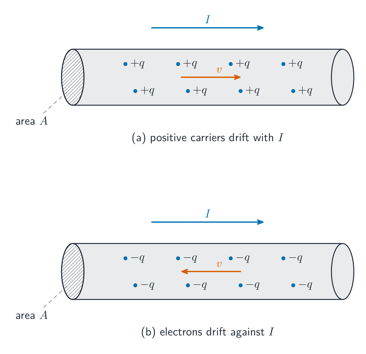
Electric current 电流 is the rate at which charge passes a cross-section of wire, $I=\dfrac{dq}{dt}$, measured in amperes 安培. Conventional current points the way positive charge would move. Microscopically, a current is a slow drift of many carriers:
$$I=nqv_dA,$$
with $n$ the number of carriers per volume, $q$ the charge each carries, $v_d$ the drift velocity 漂移速度, and $A$ the cross-sectional area 横截面积.
Worked example. A copper wire with $A=1.0\times10^{-6}\ \text{m}^2$ and $n=8.5\times10^{28}\ \text{m}^{-3}$ carries $1.7\ \text{A}$. Then $v_d=\dfrac{I}{nqA}=\dfrac{1.7}{(8.5\times10^{28})(1.6\times10^{-19})(1.0\times10^{-6})}\approx1.3\times10^{-4}\ \text{m/s}$ – the carriers drift slower than a snail, even though the signal travels near light speed.
In metal wires the carriers are actually electrons, which drift against the conventional current. Circuit diagrams still use conventional current. And "zero current" does not mean the electrons are still: they move fast in random directions, but with no net drift, so no net charge crosses the wire.
Current density 电流密度 is charge flow per unit area, $\vec{J}=nq\vec{v}_d$, linked to the field driving it by $\vec{E}=\rho\vec{J}$. In general $I=\int\vec{J}\cdot d\vec{A}$; if $J(r)$ varies across the wire, integrate it over the cross-section to get the total current. One care point: current has a direction along its wire, but it is a scalar 标量 – currents do not add as vectors, and there are no "components of current".
Worked example (non-uniform current density). In a wire of radius $a$, the current density is $J=J_0\,r/a$: zero on the axis, largest at the surface. Cut the cross-section into thin rings of area $dA=2\pi r\,dr$: $I=\int_0^a J_0\dfrac{r}{a}\,2\pi r\,dr=\dfrac{2\pi J_0}{a}\cdot\dfrac{a^3}{3}=\dfrac{2}{3}\pi a^2J_0$. That is two-thirds of what a uniform $J_0$ would give.
Explore
Drive a current
Build a simple loop and watch current flow around it from the battery.
Vocabulary
Train
| English |
|---|
| Electric current/ɪˈlektrɪk ˈkʌrənt/ |
| amperes/ˈæmpeəz/ |
| drift velocity/drɪft vəˈlɒsɪti/ |
| cross-sectional area/krɒs ˈsekʃənl ˈeərɪə/ |
| current density/ˈkʌrənt ˈdensɪti/ |
| scalar/ˈskeɪlə/ |
11.2
Electric Circuits
Syllabus
| Learning Objective | Essential Knowledge |
|---|---|
11.2.A |
Boundary statement: Unless otherwise specified, all circuit schematic diagrams will be drawn using conventional current. |
Source: College Board AP Course and Exam Description
A circuit is a set of closed loops built from wires, batteries, resistors, lightbulbs, capacitors, inductors, switches, and meters; charge can flow only around a closed path. One element can belong to several loops at once – that is what makes multi-loop problems interesting. Every analysis starts by reading the circuit diagram 电路图: trace each loop and identify which elements share the same current (series 串联) and which share the same potential difference (parallel 并联).
Three words describe a path. In a closed circuit charge can flow all the way round. In an open circuit there is a gap, such as an open switch, so no charge flows. In a short circuit a wire with no resistance joins two points, so charge flows between them with no potential difference. A diagonal arrow drawn across a symbol means the element is variable, such as a variable resistor.
Explore
Build series and parallel circuits
In series the same current flows through every bulb and voltage divides; in parallel each branch gets the full voltage. Switch mode to see the bulbs' brightness change.
Vocabulary
Train
| English |
|---|
| circuit diagram/ˈsɜːkɪt ˈdaɪəɡræm/ |
| series/ˈsɪəriːz/ |
| parallel/ˈpærəlel/ |
11.3
Resistance, Resistivity, and Ohm's Law
Syllabus
| Learning Objective | Essential Knowledge |
|---|---|
11.3.A |
|
11.3.B |
|
Source: College Board AP Course and Exam Description
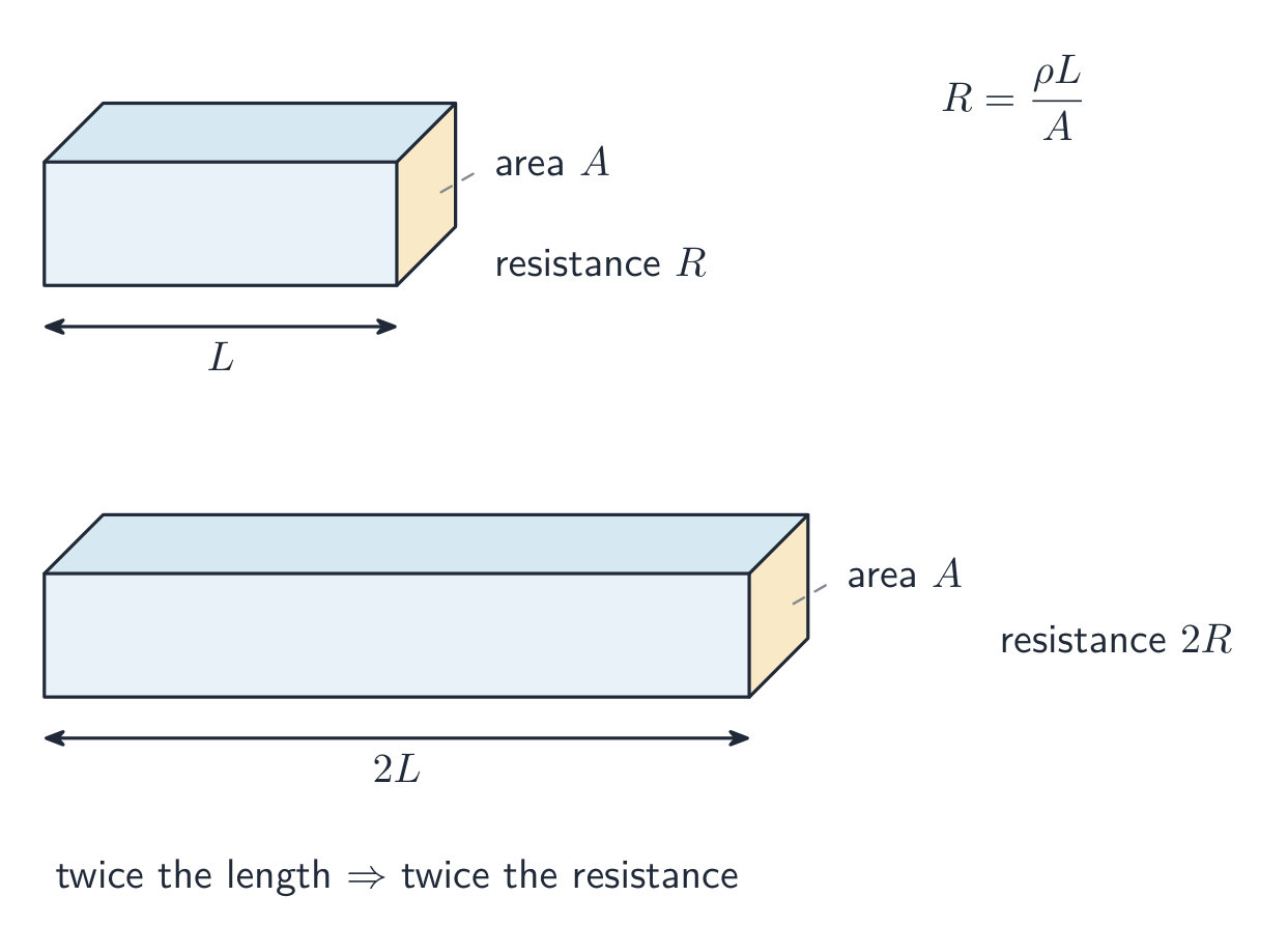
Resistance 电阻 measures how strongly an object opposes charge flow. It grows with the material's resistivity 电阻率 and the conductor's length, and shrinks with its area:
$$R=\frac{\rho\,\ell}{A}.$$
Ohm's law 欧姆定律 relates the current through an element to the potential difference across it:
$$I=\frac{\Delta V}{R}.$$
Worked example. Stretch a wire to double its length: the volume is fixed, so the area halves, and $R=\rho\ell/A$ becomes $\rho(2\ell)/(A/2)=4R$ – four times the resistance. An element is ohmic 欧姆性 if $R$ stays constant (a straight line through the origin on an $I$–$\Delta V$ graph); a lightbulb filament, which heats up, is not. For an ohmic element, the slope of an $I$-against-$\Delta V$ graph is $1/R$.
Resistivity is a property of the material. For most metals it increases with temperature: hotter atoms vibrate more and get in the way of the drifting electrons. Electrical energy turned into thermal energy in a resistor warms it and its surroundings. If the resistivity changes along a wire, add up thin slices: $R=\displaystyle\int\frac{\rho(\ell)\,d\ell}{A}$.
Worked example (resistivity that changes along a rod). A rod of length $L$ and area $A$ has $\rho(x)=\rho_0(1+x/L)$. Then $R=\dfrac{1}{A}\displaystyle\int_0^L\rho_0\Big(1+\frac{x}{L}\Big)dx=\dfrac{\rho_0}{A}\Big(L+\frac{L}{2}\Big)=\dfrac{3\rho_0L}{2A}$, between the two values for uniform $\rho_0$ and uniform $2\rho_0$, as it should be.
Explore
Apply Ohm's law
Ohm's law $V=IR$: for a fixed resistance, current is proportional to voltage. Raise the resistance and the same voltage pushes less current.
Vocabulary
Train
| English |
|---|
| Resistance/rɪˈzɪstəns/ |
| resistivity/ˌriːzɪˈstɪvəti/ |
| Ohm's law/əʊmz lɔː/ |
| ohmic/ˈəʊmɪk/ |
11.4
Electric Power
Syllabus
| Learning Objective | Essential Knowledge |
|---|---|
11.4.A |
Boundary statement: AP Physics C: Electricity & Magnetism only expects students to analyze the transfer of mechanical and electrical energy, although students should be aware that electrical energy can also be dissipated in the form of thermal energy. |
Source: College Board AP Course and Exam Description
A charge $q$ falling through a potential difference $\Delta V$ gives up energy $q\Delta V$, so the rate of energy transfer in an element is
$$P=I\,\Delta V=I^2R=\frac{(\Delta V)^2}{R}.$$
In a resistor all of it becomes heat. Use the form whose quantities you actually know – and use power to rank lightbulb brightness: brighter = more power, not necessarily more resistance. In series, the larger resistance is brighter ($P=I^2R$, same $I$); in parallel, the smaller one is ($P=\Delta V^2/R$, same $\Delta V$).
Worked example (bulb brightness). Two identical bulbs, each $6.0\ \Omega$, are joined to a $12\ \text{V}$ ideal battery. In series, each gets $6.0\ \text{V}$ and $1.0\ \text{A}$, so each uses $6.0\ \text{W}$. In parallel, each gets the full $12\ \text{V}$ and $2.0\ \text{A}$, so each uses $24\ \text{W}$: four times as bright, and the battery supplies $48\ \text{W}$ in all, so it also runs down four times as fast as the series pair (whose total is $12\ \text{W}$). Unscrew one bulb: in series the other goes out; in parallel the other is unchanged.
Explore
Read an I-V characteristic
Power is $P=IV$. A resistor's I-V line is straight, but a lamp curves as it heats and its resistance rises. The area under I-V relates to the energy delivered.
11.5
Compound Direct Current Circuits
Syllabus
| Learning Objective | Essential Knowledge |
|---|---|
11.5.A |
|
11.5.B |
|
11.5.C |
Boundary statement: Unless otherwise stated, all batteries, wires, and meters are assumed to be ideal. Circuits with batteries of different potential differences connected in parallel will not be assessed. |
Source: College Board AP Course and Exam Description
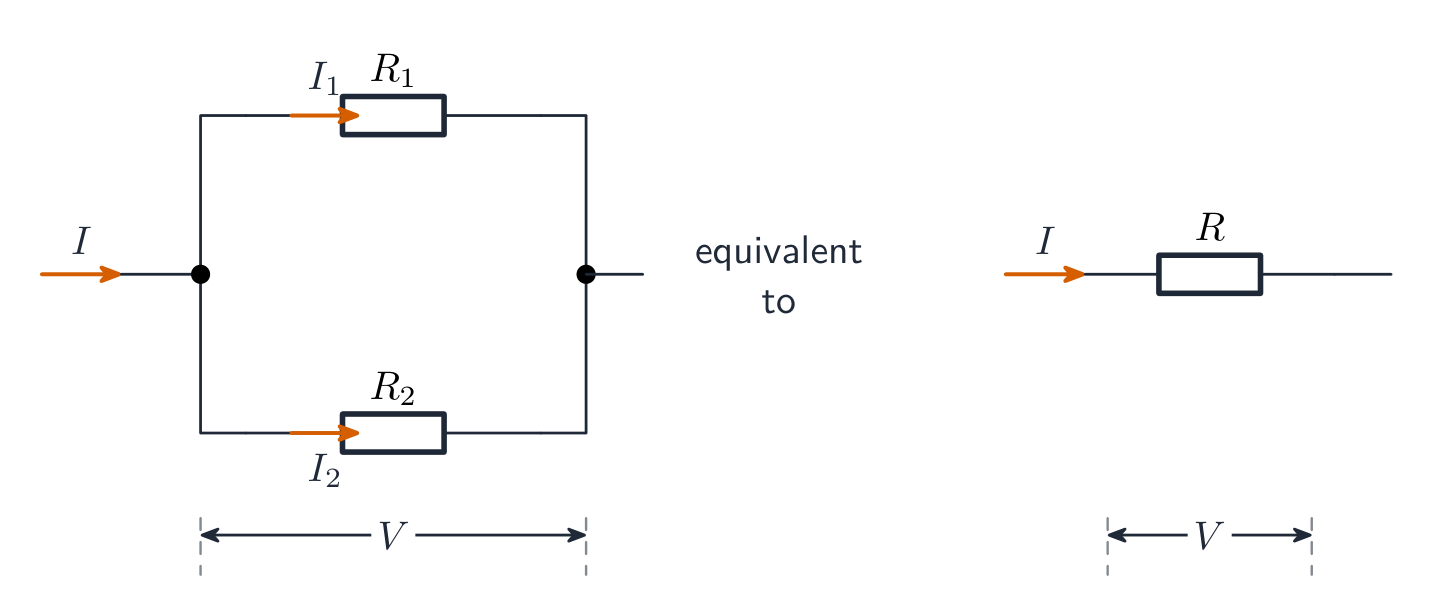
Reduce resistor networks to an equivalent resistance 等效电阻: series resistances add ($R_{\text{eq}}=R_1+R_2+\cdots$), while parallel resistances add as reciprocals ($\tfrac{1}{R_{\text{eq}}}=\tfrac{1}{R_1}+\tfrac{1}{R_2}+\cdots$ – always less than the smallest branch). Collapse the network step by step to find the battery current, then expand back out to find each element's current and voltage.
Worked example. A $12\ \text{V}$ battery drives a $4.0\ \Omega$ and a $2.0\ \Omega$ resistor in series: $R_{\text{eq}}=6.0\ \Omega$, $I=2.0\ \text{A}$, the voltages split $8.0\ \text{V}$ and $4.0\ \text{V}$, and the $4.0\ \Omega$ resistor dissipates $P=I^2R=16\ \text{W}$.
Real batteries are not ideal. Model a battery as an ideal battery 理想电池 of emf $\varepsilon$ in series with its own internal resistance 内阻 $r$. When current flows, some emf is used up inside, so the terminal voltage 端电压 – what a voltmeter across the battery actually reads – drops:
$$\Delta V_{\text{terminal}}=\varepsilon-Ir.$$
Worked example. A battery with $\varepsilon=12\ \text{V}$ and $r=0.50\ \Omega$ supplies $2.0\ \text{A}$: the terminals sit at $\Delta V=12-2.0(0.50)=11\ \text{V}$. With no current, a voltmeter reads the full $12\ \text{V}$.
Worked example (parallel branch). A $6.0\ \Omega$ and a $3.0\ \Omega$ resistor in parallel sit in series with a $4.0\ \Omega$ resistor across an ideal $12\ \text{V}$ battery. The parallel pair is $\dfrac{6.0\times3.0}{6.0+3.0}=2.0\ \Omega$, so $R_{\text{eq}}=6.0\ \Omega$ and $I=2.0\ \text{A}$. The $4.0\ \Omega$ resistor takes $8.0\ \text{V}$, leaving $4.0\ \text{V}$ across the pair: $0.67\ \text{A}$ in the $6.0\ \Omega$ and $1.33\ \text{A}$ in the $3.0\ \Omega$ branch. Check: $0.67+1.33=2.0\ \text{A}$.
Wires are treated as having no resistance because theirs is tiny next to the other elements. That fails when nothing else in the loop has resistance: a battery shorted by a bare wire drives a huge current, limited only by its internal resistance and the wire.
Meters: an ammeter 电流表 goes in series at the point whose current you want (ideal ammeter: zero resistance); a voltmeter 电压表 goes in parallel across the element (ideal voltmeter: infinite resistance). Non-ideal meters disturb the circuit they measure – a real ammeter adds series resistance, a real voltmeter steals current.
Exam skill (making a straight line). Free-response lab questions often give a table and ask you to graph two quantities that give a straight line, then read a value from its slope or intercept. To find a battery's $\varepsilon$ and $r$, connect it to a variable resistor $R$ and measure $V$ across $R$. Since $I=\dfrac{\varepsilon}{R+r}$ and $V=IR$, $V=\dfrac{\varepsilon R}{R+r}$. Take reciprocals:
$$\frac{1}{V}=\frac{1}{\varepsilon}+\frac{r}{\varepsilon}\cdot\frac{1}{R}.$$
Plot $1/V$ against $1/R$: the intercept is $1/\varepsilon$ and the slope is $r/\varepsilon$. If the best-fit line has intercept $0.111\ \text{V}^{-1}$ and slope $0.0556\ \Omega/\text{V}$, then $\varepsilon=1/0.111=9.0\ \text{V}$ and $r=0.0556\times9.0=0.50\ \Omega$. Use the line, not two data points. The same idea finds a resistivity: plot $R$ against length $\ell$ for wires of one thickness, and the slope is $\rho/A$.
Explore
Series vs parallel
Wire bulbs in parallel and compare the current and brightness with a series wiring.
Vocabulary
Train
| English |
|---|
| equivalent resistance/ɪˈkwɪvələnt rɪˈzɪstəns/ |
| ideal battery/aɪˈdɪəl ˈbætəri/ |
| internal resistance/ɪnˈtɜːnl rɪˈzɪstəns/ |
| terminal voltage/ˈtɜːmɪnl ˈvəʊltɪdʒ/ |
| ammeter/ˈæmiːtə/ |
| voltmeter/ˈvəʊltmiːtə/ |
11.6
Kirchhoff's Loop Rule

Syllabus
| Learning Objective | Essential Knowledge |
|---|---|
11.6.A |
|
Source: College Board AP Course and Exam Description
Charges moving through potential differences exchange energy ($\Delta U_E=q\Delta V$), and energy must balance around any closed path. That is Kirchhoff's loop rule 基尔霍夫回路定则:
$$\sum\Delta V=0\ \text{around any closed loop}.$$
Sign discipline wins these problems: crossing a battery from $-$ to $+$ is $+\varepsilon$; crossing a resistor with the assumed current is $-IR$ (against it, $+IR$). Write one equation per independent loop.
A graph of potential against position, as above, shows the loop rule at a glance. Here a $12\ \text{V}$ battery with $r=1.0\ \Omega$ drives $R_1=3.0\ \Omega$ and $R_2=2.0\ \Omega$, so $I=12/6.0=2.0\ \text{A}$. Ideal wires are flat lines: no resistance, no drop. The rise of $12\ \text{V}$ equals the drops $2+6+4=12\ \text{V}$.
Explore
Kirchhoff's loop rule
Around any closed loop the voltage rises equal the voltage drops. Sort each crossing.
Vocabulary
Train
| English |
|---|
| Kirchhoff's loop rule/ˈkɜːkhɒfs luːp ruːl/ |
11.7
Kirchhoff's Junction Rule
Syllabus
| Learning Objective | Essential Knowledge |
|---|---|
11.7.A |
|
Source: College Board AP Course and Exam Description
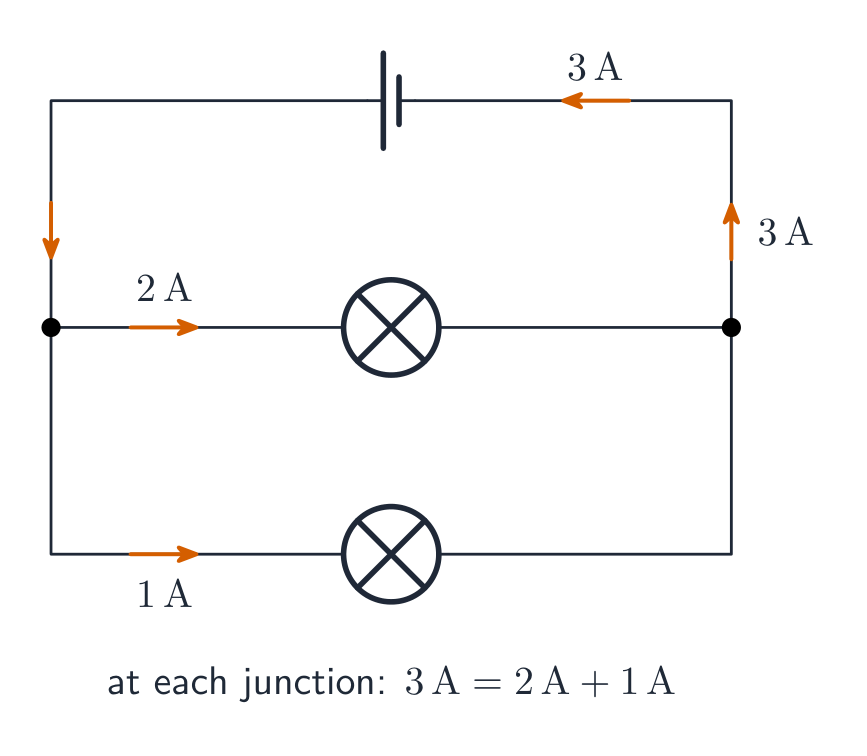
Kirchhoff's junction rule 基尔霍夫节点定则 is conservation of charge at a junction 节点:
$$\sum I_{\text{in}}=\sum I_{\text{out}}.$$
Together the two rules solve any multi-loop circuit: assign a current to each branch, write junction equations, then loop equations, and solve. A negative answer just means that current flows opposite to your assumed direction.
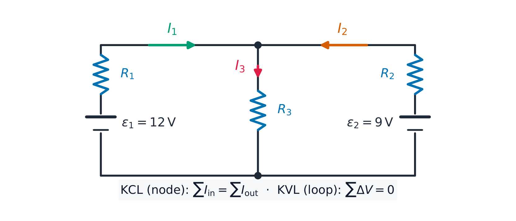
Worked example. In the circuit above, $\varepsilon_1=12\ \text{V}$ with $R_1=1.0\ \Omega$ on the left, $\varepsilon_2=9.0\ \text{V}$ with $R_2=1.0\ \Omega$ on the right, and a shared middle resistor $R_3=2.0\ \Omega$ carrying $I_3=I_1+I_2$ (junction rule). The two loop equations are
$$12=I_1+2(I_1+I_2)=3I_1+2I_2,\qquad 9=I_2+2(I_1+I_2)=2I_1+3I_2.$$
Solving: $I_1=3.6\ \text{A}$, $I_2=0.60\ \text{A}$, so $I_3=4.2\ \text{A}$ through the middle. Check with the second loop: $2(3.6)+3(0.60)=9.0$ ✓.
Explore
Split the current
Wire two parallel branches and see the current divide between them at the junction.
Vocabulary
Train
| English |
|---|
| Kirchhoff's junction rule/ˈkɜːkhɒfs ˈdʒʌŋkʃn ruːl/ |
| junction/ˈdʒʌŋkʃn/ |
11.8
Resistor-Capacitor (RC) Circuits
Syllabus
| Learning Objective | Essential Knowledge |
|---|---|
11.8.A |
|
11.8.B |
|
Source: College Board AP Course and Exam Description
Capacitor networks reduce like resistors but with the rules swapped: parallel capacitances add ($C_{\text{eq}}=C_1+C_2$), series add as reciprocals – and capacitors in series must carry the same charge on each plate, by conservation of charge. Use the equivalent capacitance 等效电容 to analyse the network, then expand back.
In an RC circuit RC电路, Kirchhoff's loop rule gives the differential equation
$$\varepsilon=R\frac{dq}{dt}+\frac{q}{C},$$
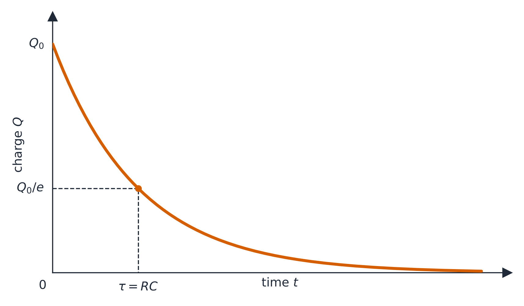
whose solutions are exponentials with time constant 时间常数 $\tau=RC$:
$$q(t)=Q\big(1-e^{-t/RC}\big)\ \text{(charging)},\qquad q(t)=Q\,e^{-t/RC}\ \text{(discharging)},\qquad i(t)=\frac{\varepsilon}{R}e^{-t/RC}.$$
The current is largest at the first instant and decays – it never "waits" for the capacitor. Learn the two limits: at $t=0$ an uncharged capacitor acts like a plain wire (maximum current); after a long time it is fully charged, no current flows in its branch, and it acts like a break. In any steady state 稳态, cover the capacitor branch with your finger, solve the resistor circuit, then read the capacitor's voltage from the element it sits across.
Worked example. With $R=5.0\ \text{k}\Omega$, $C=200\ \mu\text{F}$, and a $10\ \text{V}$ battery: $\tau=RC=1.0\ \text{s}$; initial current $\dfrac{\varepsilon}{R}=2.0\ \text{mA}$; after one time constant the charge is $q=CV(1-e^{-1})\approx1.3\times10^{-3}\ \text{C}$, about $63\%$ of full charge, and the current has fallen to $37\%$ of its initial value.
Exam skill (RC data). To find $RC$ from a discharge, record $\Delta V_C$ at regular times and plot $\ln\Delta V_C$ against $t$. Since $\ln\Delta V_C=\ln V_0-\dfrac{t}{RC}$, the graph is a straight line of slope $-1/RC$. A capacitor that takes longer than expected to reach half its final voltage has a larger $RC$ than you assumed. Charging and discharging to 50% take the same time, $RC\ln2$.
Where the exponential comes from. For discharging, there is no battery: $0=R\dfrac{dq}{dt}+\dfrac{q}{C}$. Separate the variables: $\dfrac{dq}{q}=-\dfrac{dt}{RC}$. Integrate from $Q$ at $t=0$: $\ln\dfrac{q}{Q}=-\dfrac{t}{RC}$, so $q=Qe^{-t/RC}$. A free-response question may ask for exactly these steps.
Worked example (steady state with two branches). A $12\ \text{V}$ ideal battery drives $R_1=2.0\ \Omega$ in series with $R_2=4.0\ \Omega$. A $50\ \mu\text{F}$ capacitor, in series with $R_3=10\ \Omega$, is connected across $R_2$. Just after the switch closes, the empty capacitor acts as a wire, so $R_3$ is in parallel with $R_2$: $\dfrac{4.0\times10}{14}=2.86\ \Omega$, total $4.86\ \Omega$, battery current $2.47\ \text{A}$. After a long time, no current flows in the capacitor branch: $I=12/6.0=2.0\ \text{A}$, the capacitor has the same p.d. as $R_2$, $\Delta V=8.0\ \text{V}$, and it stores $U=\tfrac12CV^2=\tfrac12(50\times10^{-6})(8.0)^2=1.6\ \text{mJ}$. Now open the battery switch. The capacitor discharges through $R_3$ and $R_2$ in series, with $\tau=(14)(50\times10^{-6})=0.70\ \text{ms}$. Its initial current is $8.0/14=0.57\ \text{A}$, and the current in $R_2$ drops at once from $2.0\ \text{A}$ to $0.57\ \text{A}$. It keeps its direction, because the capacitor's positive plate is joined to the high side of $R_2$, and then it decays to zero. All $1.6\ \text{mJ}$ stored ends up as thermal energy in the two resistors, shared in the ratio of their resistances, since they carry the same current.
Explore
Charge through a resistor
Watch the capacitor fill gradually and the charging current fade toward zero.
Vocabulary
Train
| English |
|---|
| equivalent capacitance/ɪˈkwɪvələnt kəˈpæsɪtəns/ |
| time constant/taɪm ˈkɒnstənt/ |
| steady state/ˈstedi steɪt/ |
| RC circuit/ˌɑː ˈsiː ˈsɜːkɪt/ |
11.8
Exam tips
- Relate current to charge flow $I=\tfrac{dQ}{dt}$ and use $J=\sigma E$, $R=\tfrac{\rho L}{A}$ for resistance.
- Apply Kirchhoff's laws (junction: charge; loop: energy) with consistent sign conventions.
- Analyse RC circuits with calculus: charging/discharging give exponentials with time constant $\tau=RC$.
- Combine resistors (series add, parallel reciprocal) and track power $P=IV=I^2R$.
- At $t=0$ a capacitor acts like a wire; after a long time ($t\to\infty$) it acts like an open branch.
Common mistakes
- Choosing one direction for every current and then forgetting the signs. A negative answer just means the current flows the other way; keep it.
- Getting the loop-rule sign of a resistor wrong. Crossing a resistor in the direction of the current is a drop of $IR$.
- Saying a fully charged capacitor still carries current. In the steady state it acts as a break in the circuit.
- Using $RC$ as the half-life. After one time constant the current has fallen to $37\%$; halving takes $RC\ln 2$.
- Ignoring the internal resistance when the question gives one: terminal voltage $= \varepsilon - Ir$.
- Saying the current is "used up" in a resistor. The current is the same on both sides of a series resistor; it is energy that is transferred.
- Saying that a larger resistance always makes a bulb brighter. That is true in series only; in parallel the smaller resistance is brighter.
- In a straight-line graph question, calculating with two raw data points. Use points read from your best-fit line.
- Adding currents as vectors at a junction. Current is a scalar: only "in" and "out" matter, not the angles of the wires.
Interactive lessons on this topic
Work through it step by step, with instant-check exercises.