What this course is, and how to use it
This is the sixth course in University Mechanical Engineering: mechanics of materials 材料力学 — what the load does to the part: stress, deformation and the failure conditions that decide whether a member is safe, computed on the bracket assembly the track has carried since Course 2.
Scope limit, stated once: a study course, not a degree; members are straight rods, shafts and beams of steel ($E = 200\ \mathrm{GPa}$, $G = 80\ \mathrm{GPa}$, $\sigma_y = 250\ \mathrm{MPa}$), and every number printed here is recomputed in the course suite before it ships.
- Units 6.1–6.2 load a member along its axis and about it: axial and torsion.
- Units 6.3–6.4 load it across: the diagrams, then the stresses and the sag they price.
- Unit 6.5 rotates the stress state; unit 6.6 asks when the member stops being one: buckling and failure criteria.
The habit: compute the stress state, then check it against the limit — the suite runs both steps on every member.
Axial loading
Why it matters. The tie rod that anchors the bracket is the simplest member in the assembly — and it carries every trap: stress, strain, thermal effects and static indeterminacy in one dimension.
The idea, with a picture. Normal stress 正应力 $\sigma = P/A$, strain 应变 $\varepsilon = \delta/L$, Hooke $\sigma = E\varepsilon$, and Poisson's ratio 泊松比 $\nu = 0.30$ squeezing laterally: $\varepsilon_{lat} = -\nu\varepsilon$.
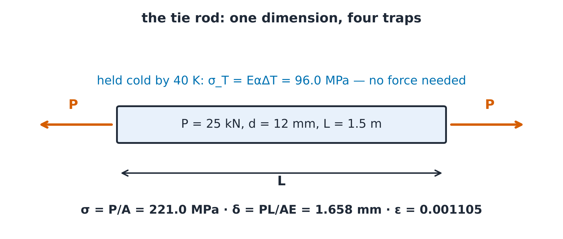
The derivation (why $\delta = PL/AE$). Substitute Hooke into the definition: $\delta = \varepsilon L = \sigma L/E = PL/(AE)$ — one line, and the member's stiffness $AE/L$ falls out of it.
Worked example 1 — the tie rod. Steel rod $d = 12\ \mathrm{mm}$, $L = 1.5\ \mathrm{m}$, $P = 25\ \mathrm{kN}$ tension: $A = \pi(0.006)^2 = 1.131 \times 10^{-4}\ \mathrm{m^2}$, so $\sigma = 25 \times 10^3/1.131 \times 10^{-4} = \mathbf{221.0}$ MPa — below $\sigma_y = 250$, safe. The elongation $\delta = PL/(AE) = 37500/(2.262 \times 10^7) = \mathbf{1.658}$ mm, and the strain $\varepsilon = 0.001105$ squeezes the diameter by $0.30 \times 0.001105 = 0.000332$, i.e. $\mathbf{3.98}\ \mu\mathrm{m}$ with $\nu = 0.30$.
Worked example 2 — held cold. The same rod fitted between rigid walls and cooled by $\Delta T = 40\ \mathrm{K}$ ($\alpha = 12 \times 10^{-6}/\mathrm{K}$) cannot contract, so $\sigma_T = E\alpha\Delta T = 200 \times 10^9 \times 12 \times 10^{-6} \times 40 = \mathbf{96.0}$ MPa tension — a load with no external force, the statically indeterminate signature.
Common mistakes. Using nominal diameter where the thread's root area governs. Adding thermal strain without the constraint that turns it into stress. Forgetting the lateral strain is negative.
Summary. $\sigma = P/A$; $\delta = PL/AE$; $\sigma_T = E\alpha \Delta T$ only when held; Poisson squeezes sideways.
Torsion
Why it matters. The drive shaft between motor and pump is the assembly's torsion 扭转 member, and its size is set by twist as often as by stress.
The idea, with a picture. For circular shafts, $\tau = T\rho/J$ — linear in radius, worst at the surface — and the angle of twist 扭转角 accumulates as $\phi = TL/(GJ)$.
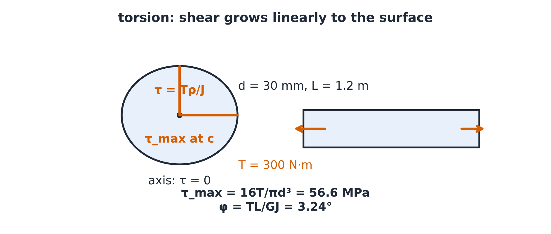
The derivation (why $J$ is geometric). Twist shears the shaft as a rigid-body rotation: $\gamma = \rho\,\phi/L$, so $\tau = G\gamma = G\rho\phi/L$ — the coefficient of $\rho$ must integrate the torque: $T = \int \rho\tau\,dA = (G\phi/L)J$, giving both formulas at once.
Worked example 1 — the drive shaft. Shaft $d = 30\ \mathrm{mm}$, $T = 300\ \mathrm{N\,m}$: $\tau_{max} = 16T/\pi d^3 = 4800/(8.482 \times 10^{-5}) = \mathbf{56.6}$ MPa. Over $L = 1.2\ \mathrm{m}$: $\phi = TL/(GJ) = 360/6362 = \mathbf{0.0566}$ rad $= \mathbf{3.24°}$.
Worked example 2 — sizing and power. A $T = 400\ \mathrm{N\,m}$ shaft at $\tau_{allow} = 60$ MPa needs $d^3 = 16 \times 400 \times 10^3/(\pi \times 60) = 33\,960\ \mathrm{mm^3}$, so $d = \mathbf{32.4}$ mm. The same torque at $180\ \mathrm{rpm}$ transmits $P = T\omega = 300 \times 18.85 = \mathbf{5.65}$ kW — stress sizes the shaft, power sells it.
Common mistakes. Using $J = \pi d^4/64$ (that is $I$) for torsion. Mixing N·mm with MPa·m⁴ in $\phi = TL/GJ$. Applying solid-shaft formulas to tubes.
Summary. $\tau_{max} = Tc/J$; $\phi = TL/GJ$; $J$ is $\pi d^4/32$ for solids; power $P = T\omega$.
Shear and bending
Why it matters. Before any stress formula, the beam's internal shear $V$ and moment $M$ must be known along the span — the diagrams are the load's biography, and every formula downstream reads them.
The idea, with a picture. Cut the beam and balance each side: $V$ and $M$ come from equilibrium section by section. Under a downward central $P = 6\ \mathrm{kN}$ on a $3\ \mathrm{m}$ simply supported span: reactions $3\ \mathrm{kN}$, $V$ steps $+3 \to -3$ kN at the load, $M$ ramps linearly to its peak $M_{max} = PL/4 = \mathbf{4.5}\ \mathrm{kN\,m}$ mid-span.
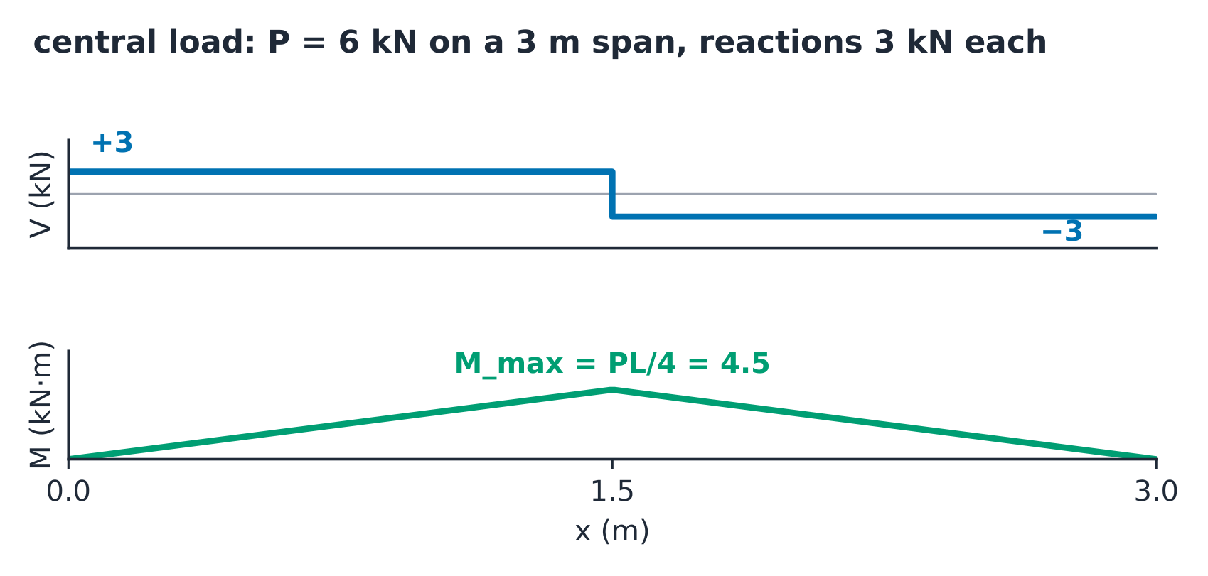
The derivation (diagrams by the differential relations). Load, shear and moment chain together: $dV/dx = -w(x)$ and $dM/dx = V$ — a point load is the limiting case, stepping $V$ and kinking $M$; a uniform load $w$ tilts $V$ linearly and bends $M$ parabolically. For $w = 2\ \mathrm{kN/m}$ over the same $3\ \mathrm{m}$ span: $V = \pm 3$ kN at the ends and $M_{max} = wL^2/8 = \mathbf{2.25}\ \mathrm{kN\,m}$ — the same shape family, no single load anywhere.
Worked example 1 — sections, with signs. Sagging is positive: the $3\ \mathrm{kN}$ left reaction lifts the left cut, so $V = +3$ kN on the left half and $M = 3x$ grows to $\mathbf{4.5}$ kN·m at the load — the sign convention is part of the answer, not decoration.
Worked example 2 — read the shape back. Hinges carry no moment ($M = 0$), free ends carry no shear, and $M$ peaks exactly where $V$ crosses zero — reading a diagram backwards recovers the loading.
Common mistakes. Dropping the sign convention (sagging vs hogging). Peaking $M$ at a support instead of the $V = 0$ point. Treating a distributed load as a point load at centre for anything but reactions and the peak.
Summary. Cut and balance; $dV/dx = -w$, $dM/dx = V$; central load $M_{max} = PL/4$, uniform load $wL^2/8$; $M$ peaks where $V = 0$.
Beam stresses and deflection
Why it matters. The diagrams price the two beam stresses — bending on the outer fibres, shear on the neutral axis — and the same moment curve, integrated twice, is the sag: the deflection 挠度.
The idea, with a picture. The flexure formula 弯曲公式 $\sigma = Mc/I$ (worst at $c$, zero at the neutral axis); transverse shear 横向剪切 $\tau = VQ/(It)$. In the rectangular section used below, its magnitude peaks at the neutral axis; the distribution depends on section shape.
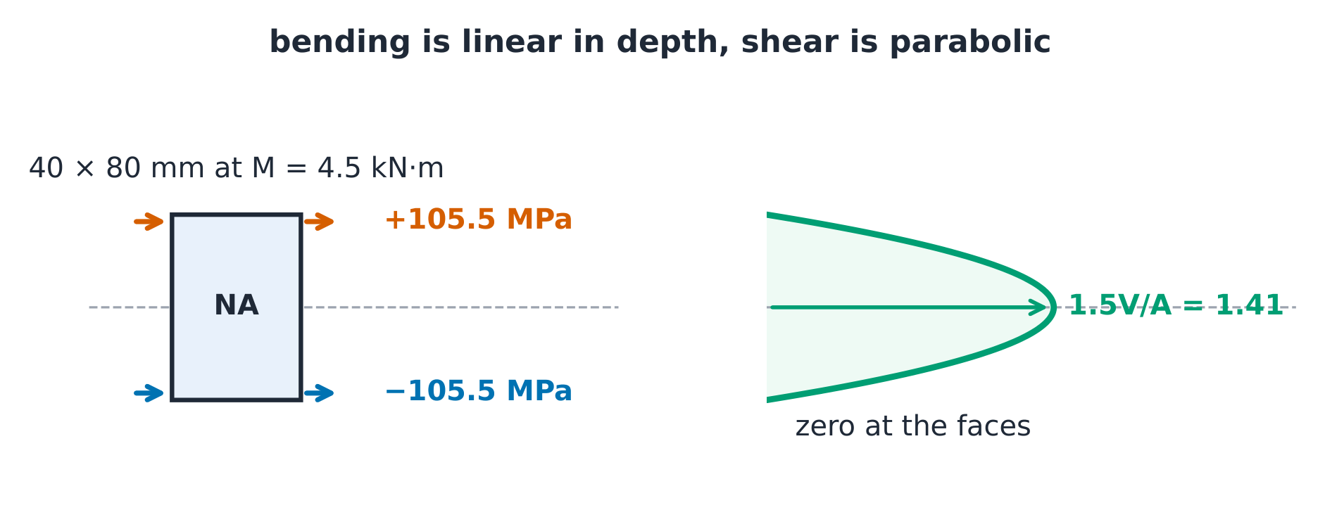
The derivation (why the rectangle's shear peaks at 1.5V/A). At the neutral axis $Q = bh^2/8$ and $t = b$, so $\tau_{max} = V(bh^2/8)/(b \cdot bh^3/12) = 1.5\,V/A$ — half again the average, the reason short wooden beams fail in shear. For the $40 \times 80\ \mathrm{mm}$ arm at $V = 3\ \mathrm{kN}$: $\tau_{max} = 1.5 \times 3000/0.0032 = \mathbf{1.41}$ MPa.
Worked example 1 — bending stress two ways. With $I = bh^3/12 = \mathbf{1.707 \times 10^{-6}}\ \mathrm{m^4}$: $\sigma = Mc/I = 180/(1.7067 \times 10^{-6}) = \mathbf{105.5}$ MPa, and the catalogue route $S = I/c = \mathbf{42.7 \times 10^{-6}}\mathrm{m^3}$ gives $\sigma = M/S = 4500/(42.7 \times 10^{-6}) = 105.5$ MPa ✓ — same number, one lookup.
Worked example 2 — the sag. The elastic curve 挠曲线 $EIv'' = M(x)$ integrates to the standard cases: central load $\delta = PL^3/(48EI) = 162000/(1.638 \times 10^7) = \mathbf{9.89}$ mm mid-span; the same section as a $1.2\ \mathrm{m}$ cantilever with $800\ \mathrm{N}$ at the tip sags $PL^3/(3EI) = 1382/(1.024 \times 10^6) = \mathbf{1.35}$ mm — and superposition prices combinations: the mid-span sag of (point + uniform) is the sum of the two sags.
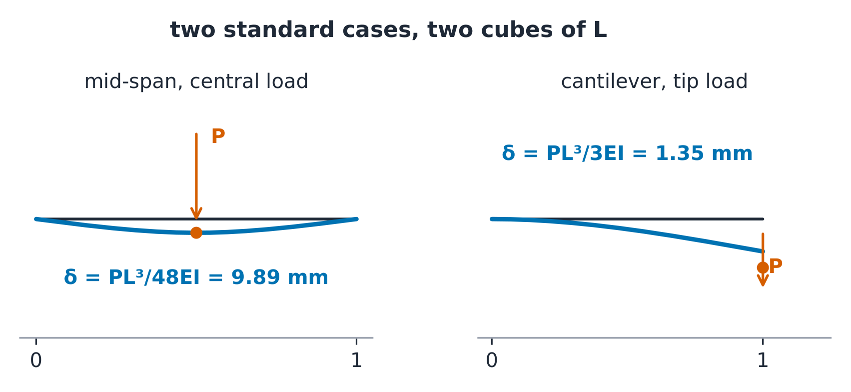
Common mistakes. Full depth for $c$ on a symmetric section. Judging stiffness by stress — a calm beam can still sag past the alignment tolerance (a serviceability limit, checked separately). Forgetting depth enters as $h^3$: double it, cut the sag eightfold.
Summary. $\sigma = Mc/I = M/S$; $\tau_{max} = 1.5V/A$ for rectangles; $\delta = PL^3/48EI$ and $PL^3/3EI$, superposed when the loads combine.
Combined stress and Mohr's circle
Why it matters. A weld, a shaft point or a gauge location carries stresses at an angle, and the extreme values — not the x-y pair — meet the failure criteria.
The idea, with a picture. Rotation of the stress element is Mohr's circle 莫尔圆: centre $\sigma_{avg} = (\sigma_x + \sigma_y)/2$, radius $R = \sqrt{((\sigma_x - \sigma_y)/2)^2 + \tau_{xy}^2}$.
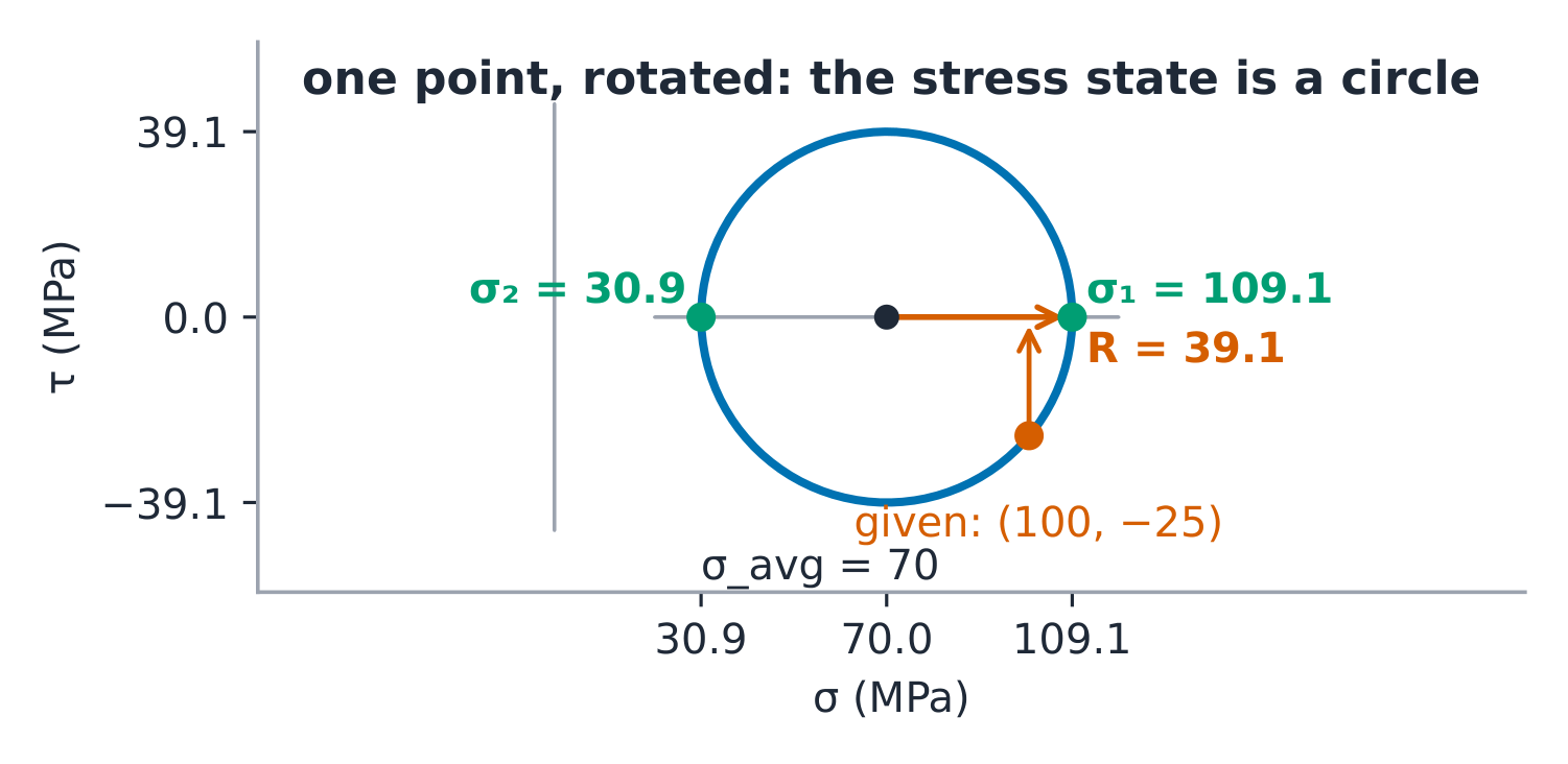
The derivation (why the circle). Equilibrium of a wedge cut at angle $\theta$ gives the transformation equations; eliminating $\theta$ leaves $(\sigma - \sigma_{avg})^2 + \tau^2 = R^2$ — a circle in the $\sigma$-$\tau$ plane that turns through $2\theta$ as the element turns $\theta$.
Worked example 1 — one point, rotated. A bracket point carries $\sigma_x = 100$, $\sigma_y = 40$, $\tau_{xy} = 25$ MPa: $\sigma_{avg} = 70$, $R = \sqrt{30^2 + 25^2} = \sqrt{1525} = \mathbf{39.1}$ MPa, so the principal stresses 主应力 $\sigma_1 = 70 + 39.1 = \mathbf{109.1}$ and $\sigma_2 = 70 - 39.1 = \mathbf{30.9}$ MPa sit at $\theta_p = \tan^{-1}(50/60)/2 = 19.9°$ — and the absolute-maximum shear, with both principals positive, is $\sigma_1/2 \approx \mathbf{54.5}$ MPa.
Worked example 2 — opposite signs. Swap the second normal stress to $-40$ MPa: the centre drops to 40 and $R = \sqrt{80^2 + 30^2} = \mathbf{85.4}$ MPa, so $\sigma_1 = \mathbf{125.4}$, $\sigma_2 = \mathbf{-45.4}$ MPa — now the principals straddle zero and the absolute-maximum shear IS the radius, $85.4$ MPa ✓: the sign pattern picks the answer.
Common mistakes. Halving the wrong angle (the circle turns twice the physical angle). Using in-plane $R$ as the absolute maximum when the principals share a sign. $Q$ as a force — it is a first moment of area.
Summary. Centre $\sigma_{avg}$, radius $R$; principals on the $\tau = 0$ axis; absolute-maximum shear is $\sigma_1/2$ for same-sign principals, $R$ otherwise.
Buckling and failure criteria
Why it matters. A slender push member fails sideways at a fraction of yield, and a computed stress state still needs a criterion to be judged against — buckling 屈曲 and failure criteria close the course.
The idea, with a picture. For an ideal slender elastic column, Euler’s load is $P_{cr} = \pi^2EI/(KL)^2$, with $K=1$ for pinned ends; below the transition slenderness $\lambda_t = \sqrt{2\pi^2E/\sigma_y}$, the Johnson parabola $\sigma_{cr} = \sigma_y - (\sigma_y\lambda)^2/(4\pi^2E)$ takes over, meeting Euler exactly at $\sigma_{cr} = \sigma_y/2$.
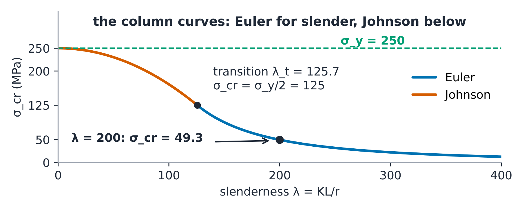
The derivation (why Euler divides by $L^2$). A pinned-pinned column bows into a half-sine; balancing the internal moment $EIv''$ against $-Pv$ admits that shape only at $P = \pi^2EI/L^2$ — the longer the member, the softer the spring it becomes, quadratically.
Worked example 1 — the strut, with a safety factor. Steel rod $d = 20\ \mathrm{mm}$, $L = 1.0\ \mathrm{m}$ pinned-pinned: $I = 7.854 \times 10^{-9}\ \mathrm{m^4}$, so $P_{cr} = \pi^2 \times 200 \times 10^9 \times 7.854 \times 10^{-9} = \mathbf{15.5}$ kN, at $\sigma_{cr} = \mathbf{49.3}$ MPa. Slenderness $\lambda = KL/r = 1000/5 = \mathbf{200}$ — well past $\lambda_t = \mathbf{125.7}$, so Euler applies; at $\lambda = 60$ Johnson gives $250 - 28.5 = \mathbf{221.5}$ MPa. At a design factor $n = 2.5$: $P_{allow} = P_{cr}/n = \mathbf{6.2}$ kN.
Worked example 2 — judging the stress state. The rod under eccentric loading 偏心加载: $30\ \mathrm{mm}$, $P = 5\ \mathrm{kN}$ at $e = 60\ \mathrm{mm}$ carries axial $7.07$ plus bending $Pec/I = 300 \times 0.015/(3.976 \times 10^{-8}) = \mathbf{113.2}$ MPa, peaking at $\mathbf{120.3}$ MPa on the far fibre. Von Mises on the Mohr example's principals $(109.1, 30.9)$: $\sigma' = \sqrt{\sigma_1^2 - \sigma_1\sigma_2 + \sigma_2^2} = \mathbf{97.4}$ MPa — under the 250 MPa yield, while max-shear reads $\tau_{max} = \mathbf{39.1}$ against its $\sigma_y/2 = \mathbf{125}$ MPa limit: both criteria agree, no yield.
Common mistakes. Applying Euler below $\lambda_t$ (it then exceeds yield — impossible). Fixing $K$ by habit instead of the end conditions. Using the failure criterion on the x-y stresses instead of the principals. quoting an allow load without its factor.
Summary. $P_{cr} = \pi^2EI/(KL)^2$ for $\lambda > \lambda_t$, Johnson below; design at $P_{cr}/n$; judge states by von Mises $\sigma'$ or max shear on the principals.