From a phone signal to its battery
Your phone receives waves and uses electrical energy. These seem different, but both depend on energy transfer. Waves 波 carry energy without carrying matter along with them. A circuit transfers energy through moving charge.
This reference covers WPH12 Waves and Electricity, specification statements 33–80. The paper lasts 90 minutes and carries 80 marks. Use the formula list to support your reasoning. Explain why an equation fits the situation, show conversions, and finish comparisons with a conclusion.
Wave quantities and graphs
A vibrating source repeats its motion. The amplitude 振幅 is the greatest displacement from equilibrium. Equilibrium 平衡位置 means the resting position. The period 周期 $T$ is the time for one complete vibration. The frequency 频率 $f$ is the number of complete vibrations each second; its unit is hertz, Hz.
The wavelength 波长 $\lambda$ is the distance between nearest points vibrating in phase. The wave speed 波速 $v$ is the speed at which a fixed phase, such as a crest, travels. It is not the speed of a vibrating particle.
- A transverse wave 横波 has vibrations perpendicular to its direction of travel. A rope moves up and down while its disturbance travels along the rope.
- A longitudinal wave 纵波 has vibrations parallel to its direction of travel. Sound has compressions 密部, where pressure and density are higher, and rarefactions 疏部, where they are lower.
- Air molecules move back and forth about their resting positions. They do not travel from the speaker to your ear with the sound.
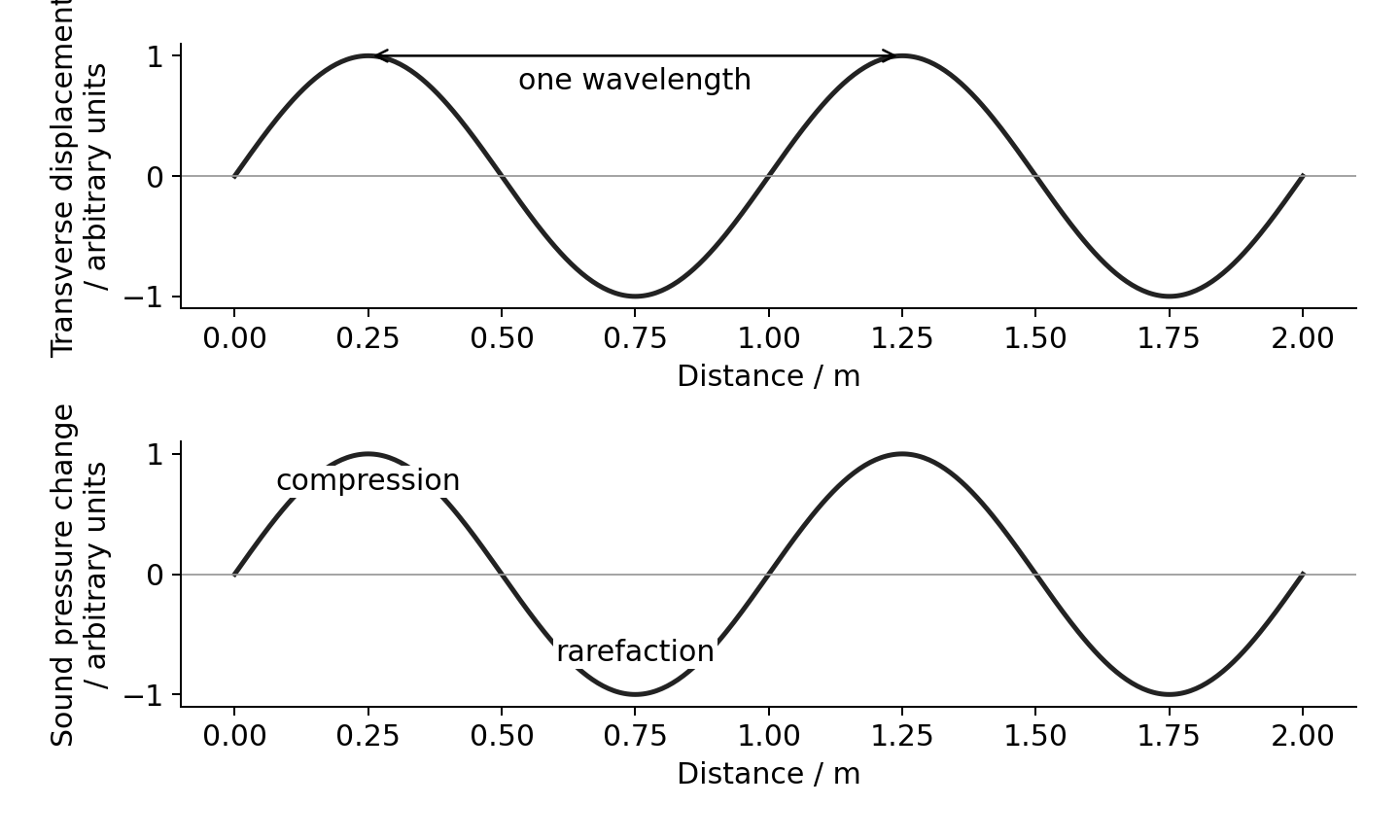
Read the horizontal axis first
A displacement–distance graph is a snapshot. The separation of neighbouring crests gives $\lambda$. A displacement–time graph follows one particle. The separation of neighbouring peaks gives $T$. The same curve shape can represent either graph, but the quantities are different.
For a longitudinal wave, a pressure–distance graph shows compressions at pressure maxima. A molecular displacement–distance graph shows displacement along the direction of travel. Maximum compression occurs where displacement changes most rapidly towards the neighbouring molecules. Pressure maximum and displacement maximum are not at the same place; their patterns are one-quarter wavelength apart in a sinusoidal travelling sound wave.
Worked example. A microphone records 12 complete cycles in $0.030\ \text{s}$. Sound travels at $340\ \text{m s}^{-1}$. Find its frequency and wavelength.
- Known: cycle count, total time and speed. Frequency counts cycles per second; the wave equation then links speed to wavelength.
$$f = \frac{N}{t} = \frac{12}{0.030\ \text{s}} = 400\ \text{Hz}$$$$v = f\lambda \quad\Rightarrow\quad \lambda = \frac{v}{f} = \frac{340\ \text{m s}^{-1}}{400\ \text{Hz}} = 0.85\ \text{m}$$
- Check: one cycle takes $T=1/f=0.0025\ \text{s}$. Twelve cycles take the stated $0.030\ \text{s}$.
Superposition and standing waves
A wavefront 波阵面 joins points at the same phase. Phase 相位 describes the stage of a vibration cycle. One complete cycle corresponds to $360^\circ$ or $2\pi$ radians.
Superposition 叠加 means adding the displacements of overlapping waves at each point. Interference 干涉 is the resulting reinforcement or cancellation. Coherent sources 相干波源 have the same frequency and a constant phase difference. Their phase difference need not be zero.
For waves of the same wavelength, the phase difference caused by a path difference 路程差 $\Delta x$ is:
For sources initially in phase, path differences $0,\lambda,2\lambda,\ldots$ give constructive interference. Half-integer wavelength differences give destructive interference. Complete cancellation also needs equal amplitudes. If sources start with a phase difference, include it too.
Worked example. Two in-phase speakers produce wavelength $0.80\ \text{m}$. Their paths to a microphone differ by $1.20\ \text{m}$.
- Known: path difference and wavelength. Convert path difference into cycles, then phase.
$$\Delta\phi = \frac{\Delta x}{\lambda}\,360^\circ = \frac{1.20}{0.80}\,360^\circ = 540^\circ$$
- $540^\circ$ is equivalent to $180^\circ$. The waves arrive in opposite phase and interfere destructively. The sound need not become silent if the arriving amplitudes differ.
How a standing wave forms
A standing wave 驻波 forms when two waves of the same frequency and similar amplitude travel in opposite directions and superpose. Reflection at a fixed string end supplies the returning wave.
- A node 波节 always has zero displacement. An antinode 波腹 has the largest vibration amplitude.
- Adjacent nodes are $\lambda/2$ apart. A node and its nearest antinode are $\lambda/4$ apart.
- Points between the same pair of nodes vibrate in phase. Points in neighbouring sections vibrate in opposite phase.
- All points have the same frequency, except that a node does not vibrate. Amplitude depends on position.
- An ideal standing wave has no net energy transfer along it. A travelling wave carries energy along its direction of travel.
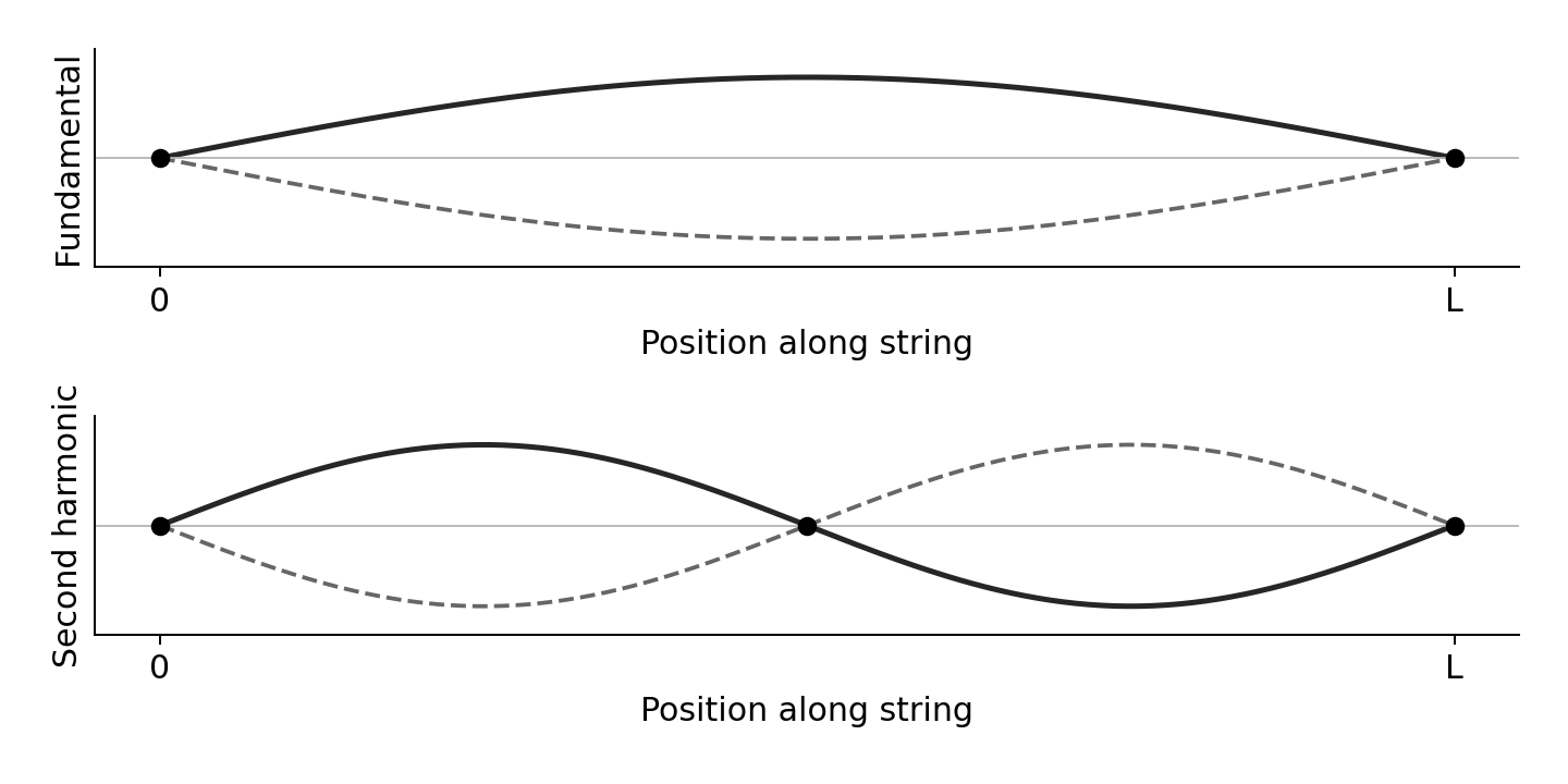
For a string fixed at both ends, length $L$ contains a whole number $k$ of half-wavelengths:
Here $T$ is tension 张力, not period; $\mu$ is mass per unit length 线密度 in $\text{kg m}^{-1}$. The fundamental has $k=1$. At fixed mode, frequency increases with $\sqrt{T}$, decreases with $L$, and decreases with $\sqrt{\mu}$.
Worked example. A $0.60\ \text{m}$ string has $\mu=1.5\times10^{-3}\ \text{kg m}^{-1}$ and tension $24\ \text{N}$. Find its fundamental frequency.
- Known: length, tension and linear density. The fundamental fits half a wavelength between the fixed ends.
$$v = \sqrt{\frac{T}{\mu}} = \sqrt{\frac{24}{1.5\times10^{-3}}}\ \text{m s}^{-1} = 126\ \text{m s}^{-1}$$$$f = \frac{v}{2L} = \frac{126\ \text{m s}^{-1}}{2\times0.60\ \text{m}} = 105\ \text{Hz}$$
- Doubling tension multiplies frequency by $\sqrt{2}$, rather than by two.
Standing sound in a closed tube
In the simplest standing sound wave in a tube closed at one end, the closed end is a molecular displacement node. The open end is approximately a displacement antinode. This fits one-quarter wavelength into the effective tube length, so $L_{effective}=\lambda/4$. The pressure pattern is reversed: the closed end is a pressure antinode. Do not call a pressure node a displacement node. Real tubes have a small open-end correction; use an effective length if the question supplies it.
Worked example. A closed tube has effective length $0.20\ \text{m}$ and fundamental frequency $425\ \text{Hz}$. The end conditions give $\lambda=4L=0.80\ \text{m}$; then $v=f\lambda=425\times0.80=340\ \text{m s}^{-1}$. A string fixed at both ends instead fits half a wavelength in its fundamental. Choose from the end conditions, not from the word “standing”.
Core practical 4: speed of sound
Use a signal generator, speaker, movable microphone and two-beam oscilloscope 双踪示波器. Connect one oscilloscope channel to the generator reference signal and the other to the microphone output. Both traces have the same frequency.
- Keep frequency constant. Move the microphone along a measured line away from the speaker. Find a position where the traces are in phase.
- Move to another in-phase position. Consecutive in-phase positions are one wavelength apart. Measure across several wavelengths and divide by their number.
- Read the period from the time-base scale: count horizontal divisions across several cycles, then divide. Find $f=1/T$ and use $v=f\lambda$.
- Repeat positions and frequencies. Keep the microphone on the speaker axis. Reduce reflected sound by working away from walls. Measure position from a fixed microphone reference point.
Measuring several wavelengths reduces the percentage uncertainty in the distance. Measuring several periods does the same for time. A resonance-tube experiment can also measure sound speed, but it does not replace this specified practical.
Core practical 5: vibrating string
Use a vibration generator driven by a signal generator. Run the string over a pulley to a hanging mass. The tension is about $mg$ when pulley friction is small. Increase frequency until a clear standing-wave pattern forms.
- Investigate tension: keep $L$, $\mu$ and mode fixed. Vary hanging mass. Plot $f^2$ against $T$; the gradient for the fundamental is $1/(4L^2\mu)$.
- Investigate length: keep tension, string type and mode fixed. Plot $f$ against $1/L$.
- Investigate linear density: measure string mass and length, $\mu=m/l$. Use different strings with fixed tension, vibrating length and mode. Plot $f^2$ against $1/\mu$.
- Measure length between the end nodes. Find the resonance from both higher and lower frequencies and repeat. Secure the stand and keep clear of falling masses.
Intensity, refraction and polarisation
Intensity 强度 is power per unit area perpendicular to the energy flow:
Its unit is $\text{W m}^{-2}$. For a receiver, incident power is $P=IA$. Useful output is smaller if efficiency is below 100%. Convert area carefully: $1\ \text{cm}^2=10^{-4}\ \text{m}^2$.
Worked example. Radiation intensity is $800\ \text{W m}^{-2}$ over a $25\ \text{cm}^2$ solar cell. Efficiency is 20%. Can it supply $0.50\ \text{W}$?
- Known: intensity, area, efficiency. First find incident power, then useful power.
$$P_{\text{in}} = IA = 800\ \text{W m}^{-2}\times25\times10^{-4}\ \text{m}^2 = 2.0\ \text{W}$$$$P_{\text{out}} = \eta P_{\text{in}} = 0.20\times2.0\ \text{W} = 0.40\ \text{W}$$
- $0.40\ \text{W}<0.50\ \text{W}$, so it cannot supply the required useful power.
Refraction and total internal reflection
Refraction 折射 is a change in wave direction when speed changes at an interface. A ray entering along the normal changes speed without changing direction. The normal 法线 is perpendicular to the boundary. Measure all ray angles from it.
The refractive index 折射率 $n$ compares vacuum light speed $c$ with speed in the material. Frequency stays constant across the boundary, so wavelength changes with speed. Entering higher $n$ bends the ray towards the normal; entering lower $n$ bends it away.
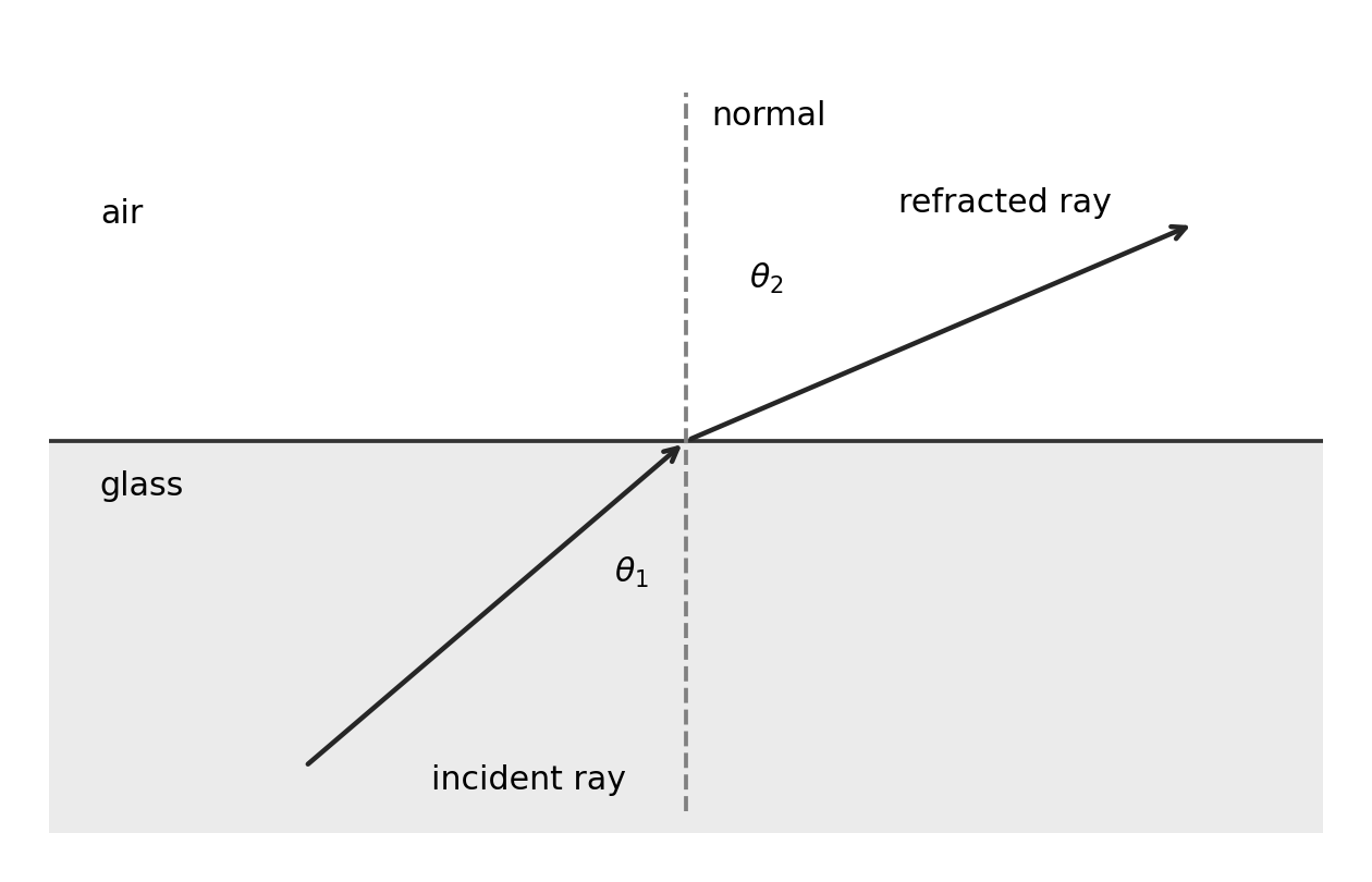
Total internal reflection 全反射 requires travel from higher to lower refractive index and incidence greater than the critical angle 临界角 $C$.
At $C$ the refracted angle is $90^\circ$; call incidence greater than $C$ total internal reflection. Below $C$, some energy is normally reflected and some transmitted. An optical fibre uses a higher-index core and lower-index cladding. Raising the cladding index raises the critical angle and can stop a previously reflected ray being trapped.
Worked example. Light travels from glass of index 1.50 into air. Does an incidence angle of $45^\circ$ produce total internal reflection?
- Known: the two indices and incidence angle. Find the boundary angle before comparing.
$$C = \sin^{-1}\left(\frac{n_2}{n_1}\right) = \sin^{-1}\left(\frac{1.00}{1.50}\right) = 41.8^\circ$$
- The light travels towards lower index and $45^\circ>41.8^\circ$. Both conditions hold, so total internal reflection occurs.
Measuring refractive index
Place a rectangular transparent block on paper and trace its outline. Use a narrow ray-box beam. Mark two points on the incident ray and two on the emerging ray. Remove the block and join the boundary points to reconstruct the ray inside. Draw the normal at entry and measure incidence $i$ and refraction $r$ with a protractor.
Repeat for several incidence angles, keeping the same material and light colour. Plot $\sin i$ vertically against $\sin r$ horizontally. For air into the block, the gradient is the block's refractive index relative to air. Use a large triangle on a best-fit line. Narrow beams and widely separated ray marks reduce direction uncertainty. Very small angles give large percentage angle uncertainties.
Plane polarisation
Plane polarisation 平面偏振 restricts transverse vibrations to one plane containing the propagation direction. Unpolarised light has vibrations in many planes. A polariser transmits one vibration direction. Rotate a second polariser: parallel transmission directions give maximum brightness; perpendicular directions ideally give darkness. The ray still travels forward; its vibration direction changes selection.
Longitudinal waves cannot be plane polarised because their vibration is already along propagation. Polarisation is therefore evidence that light is transverse.
Diffraction and pulse-echo
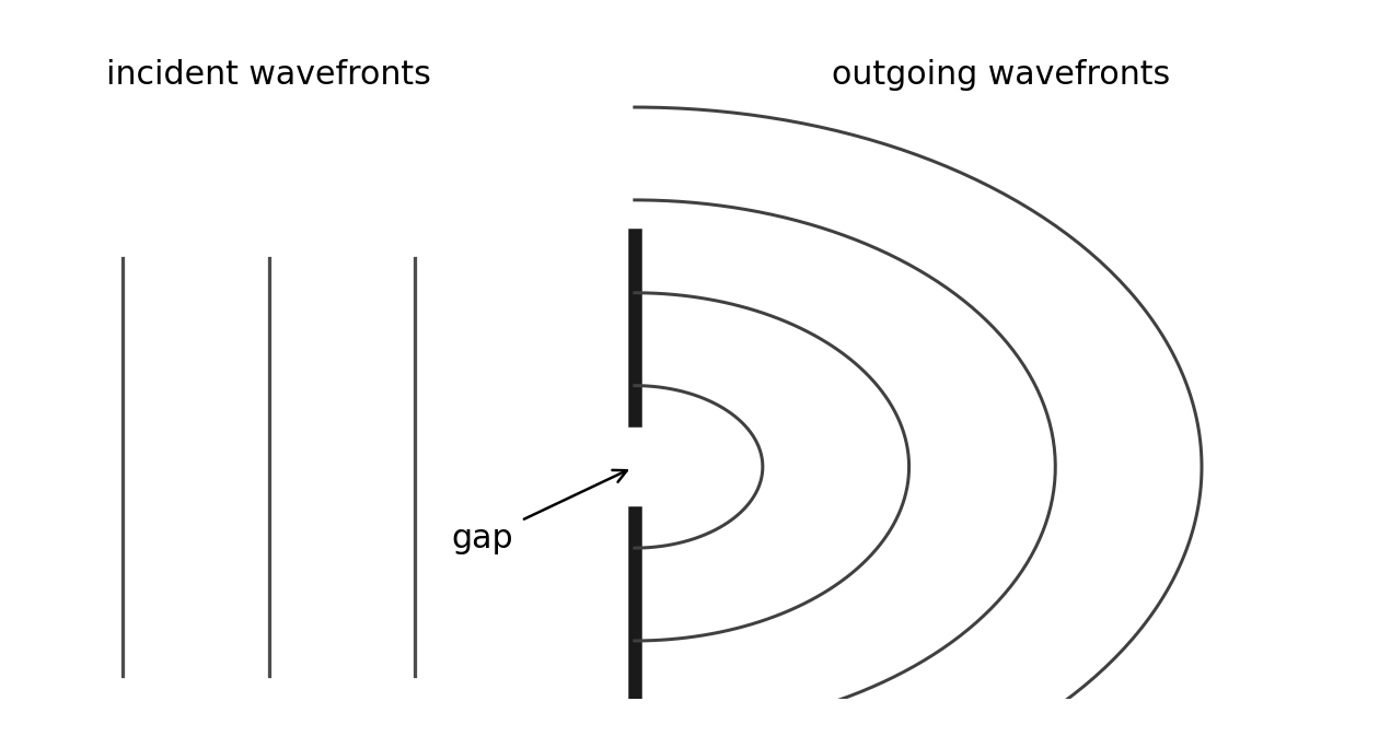
Diffraction 衍射 is the spreading of waves at a gap or edge. Spreading is greater when the gap width is comparable to the wavelength. A wide gap still diffracts at its edges, but the central wave spreads less.
In Huygens' construction 惠更斯作图法, each point on a wavefront acts as a source of secondary wavelets. Draw wavelets of equal radius after the same time. Their forward common tangent gives the new wavefront. At a narrow gap only a small part of the original front supplies wavelets, so the emerging fronts spread widely. This explains spreading without inventing a change of frequency at the slit.
Gratings and core practical 6
A diffraction grating 衍射光栅 contains many equally spaced slits. Bright maxima occur when contributions from neighbouring slits arrive in phase:
Here $k$ is the integer order 级次, $d$ is slit spacing, and $\theta$ is measured from the straight-through direction. The equation assumes normal incidence. If the grating has $N$ lines per metre, $d=1/N$. Do not confuse grating order with refractive index; printed papers may use $n$ for either.
Worked example. A grating has 600 lines per millimetre. First-order light appears at $18.0^\circ$. Find its wavelength.
- Known: line density and first-order angle. Convert line density before taking its reciprocal.
$$d = \frac{1}{N} = \frac{1}{600\times10^3\ \text{m}^{-1}} = 1.67\times10^{-6}\ \text{m}$$$$\lambda = \frac{d\sin\theta}{k} = \frac{1.67\times10^{-6}\ \text{m}\times\sin18.0^\circ}{1} = 5.15\times10^{-7}\ \text{m}$$
- This is $515\ \text{nm}$. Check each proposed higher order using $k\lambda/d\leq1$.
For CP6, aim a low-power laser normally at a grating and place a screen perpendicular to the central beam. Measure screen distance $D$ and displacement $x$ from the central spot to an order. Use $\tan\theta=x/D$, then the grating equation. Average corresponding left/right displacements, repeat distances, and use higher visible orders where measurement is clear. Measure from the grating to the screen, not from the laser casing. Do not substitute $\sin\theta=x/D$ unless a justified small-angle approximation is acceptable. Never look into the beam; keep it below eye level and stop stray beams.
Electrons also show wave behaviour
An electron beam passing through a thin crystal produces a diffraction pattern. Regular atom spacing provides the diffracting structure. Changing electron momentum changes the pattern spacing. This is evidence of wave behaviour; particles travelling along simple straight paths alone cannot explain the diffraction maxima.
The de Broglie wavelength 德布罗意波长 is:
For a non-relativistic electron, $p=mv$. If it gains kinetic energy by crossing a potential difference, $E_k=eV$ and $p=\sqrt{2mE_k}$. Use these links only when the question gives or requires that energy relation.
Worked example. An electron has momentum $2.0\times10^{-24}\ \text{kg m s}^{-1}$. With $h=6.63\times10^{-34}\ \text{J s}$:
Increasing momentum reduces wavelength. Electrons have both particle and wave properties; diffraction does not mean that an electron becomes a sound wave.
Reflection, transmission and echoes
At an interface, part of a wave's energy may be transmitted 透射 and part reflected. A reflected pulse can locate a boundary. In pulse-echo 脉冲回波, measured delay includes the outward and return journeys:
Worked example. Ultrasound travels in metal at $5900\ \text{m s}^{-1}$. An echo returns after $12\ \mu\text{s}$.
The boundary is $35\ \text{mm}$ away, not $71\ \text{mm}$. A nearby echo may overlap the transmitted pulse. Shorter pulse duration reduces this blind region and separates close echoes. Shorter wavelength helps detect or distinguish smaller features. These are related limits, but pulse duration and wavelength are not the same quantity. Use the speed in the actual material, not automatically the speed in air.
Photons and the photoelectric effect
Wave ideas explain interference, diffraction and polarisation. They did not explain all observations of energy transfer. Photons 光子 describe discrete packets of electromagnetic energy:
Historically, interference and diffraction supported wave models of light. Quantum ideas developed to explain observations including the photoelectric effect and atomic spectra. Modern physics uses both wave and photon descriptions according to the measurement. A successful new model must explain evidence that the older model explains too.
One photon and one electron
In the photoelectric effect 光电效应, a surface electron absorbs a photon and may escape. The work function 逸出功 $\phi$ is the minimum energy needed to remove an electron from the surface. The threshold frequency 极限频率 is $f_0=\phi/h$.
- Below threshold, increasing intensity does not cause emission in the usual single-photon model.
- Above threshold, higher frequency raises maximum kinetic energy. A graph of $E_{k,\max}$ against $f$ has gradient $h$, frequency intercept $f_0$ and extrapolated energy intercept $-\phi$.
- At fixed frequency above threshold, higher intensity supplies more photons per second. More electrons can be emitted per second, so the saturation photocurrent rises. Their maximum kinetic energy does not rise.
- Emission starts without the energy-building delay predicted by a simple continuous-wave energy model, even at low intensity above threshold.
- Electrons escape with a range of kinetic energies. Some lose more energy within the material. The equation describes the largest energy, not every electron's energy.
The electronvolt 电子伏特 is an energy unit: $1\ \text{eV}=1.60\times10^{-19}\ \text{J}$. It is not a unit of potential difference. A stopping potential $V_s$ just prevents even the fastest photoelectrons reaching the collector, so $eV_s=E_{k,\max}$.
Worked example. Light of frequency $8.0\times10^{14}\ \text{Hz}$ reaches a surface with work function $2.0\ \text{eV}$.
- Known: photon frequency and work function. Convert the work function into joules before subtracting.
$$\phi = 2.0\times1.60\times10^{-19}\ \text{J} = 3.20\times10^{-19}\ \text{J}$$$$E_{k,\max} = hf-\phi = 6.63\times10^{-34}\ \text{J s}\times8.0\times10^{14}\ \text{Hz}-3.20\times10^{-19}\ \text{J} = 2.10\times10^{-19}\ \text{J}$$$$V_s = \frac{E_{k,\max}}{e} = \frac{2.10\times10^{-19}\ \text{J}}{1.60\times10^{-19}\ \text{C}} = 1.3\ \text{V}$$
- The positive kinetic energy confirms that this frequency is above threshold. A negative subtraction would mean no emission, not negative kinetic energy.
Atomic line spectra
Atoms have discrete energy levels 分立能级. An electron moving down between two allowed levels emits a photon. Moving up requires absorption of the matching energy:
A line spectrum has particular frequencies because only certain level differences are allowed. The largest downward energy difference gives the highest frequency and shortest wavelength. Count possible transitions by checking level pairs and which upper levels are populated; do not automatically count the number of levels as the number of lines.
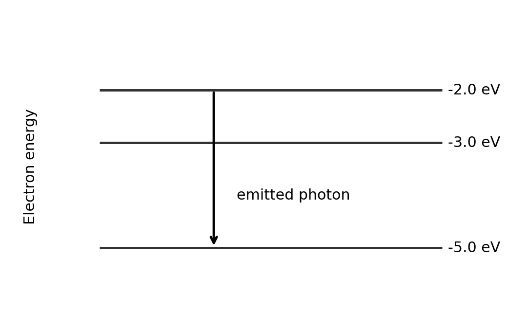
Worked example. An electron drops from $-2.0\ \text{eV}$ to $-5.0\ \text{eV}$.
Photon absorption in a material does not always eject an electron from its surface. Excitation followed by emission, for example in a light-activated material, is not automatically the photoelectric effect.
Current, resistance and circuits
Current 电流 is the rate of charge flow. Conventional current follows the direction positive charges would move. In a metal, electrons drift in the opposite direction.
One ampere is one coulomb per second. Potential difference 电势差 $V$ is energy transferred per unit charge between two points. Resistance $R$ is defined by the ratio $V/I$ at an operating point. Ohm's law 欧姆定律 is the extra condition $I\propto V$ when temperature and other physical conditions stay constant. Not every resistor or component obeys it.
Worked example. A current of $0.40\ \text{A}$ flows for $30\ \text{s}$. Find the number of electrons passing a point.
Conservation gives the circuit rules
Charge conservation 电荷守恒 means charge does not build up at a steady-current junction. Total current entering equals total current leaving. Current is not used up by a resistor.
Energy conservation 能量守恒 means the total energy supplied per coulomb around a complete loop equals the energy transferred per coulomb. The sum of voltage rises equals the sum of voltage drops.
For series resistors, the same current passes through each and their potential differences add:
For parallel resistors, each has the same p.d. and the branch currents add:
A parallel combination has smaller resistance than its smallest branch resistance. A voltmeter connects in parallel across a component; an ideal voltmeter has infinite resistance. An ammeter connects in series; an ideal ammeter has zero resistance.
Worked example. A $6.0\ \Omega$ resistor is parallel to $3.0\ \Omega$. The combination is in series with $4.0\ \Omega$ across $12\ \text{V}$.
- Known: circuit arrangement. Reduce the parallel section first, then apply the series rule.
$$R_p = \left(\frac{1}{6.0}+\frac{1}{3.0}\right)^{-1}\ \Omega = 2.0\ \Omega$$$$I = \frac{V}{R_p+R_s} = \frac{12\ \text{V}}{(2.0+4.0)\ \Omega} = 2.0\ \text{A}$$$$V_p = IR_p = 2.0\ \text{A}\times2.0\ \Omega = 4.0\ \text{V}$$$$I_{6} = \frac{V_p}{6.0\ \Omega} = 0.67\ \text{A} \qquad I_{3} = \frac{V_p}{3.0\ \Omega} = 1.33\ \text{A}$$
- Check: branch currents add to $2.0\ \text{A}$. The remaining series resistor has an $8.0\ \text{V}$ drop.
Power and component graphs
Electrical power 电功率 is energy transferred each second. Substituting $V=IR$ into $P=VI$ gives the other forms:
Use voltage across, and current through, the same component. The resistance forms apply to its operating-point resistance; do not assume a heating lamp has constant resistance.
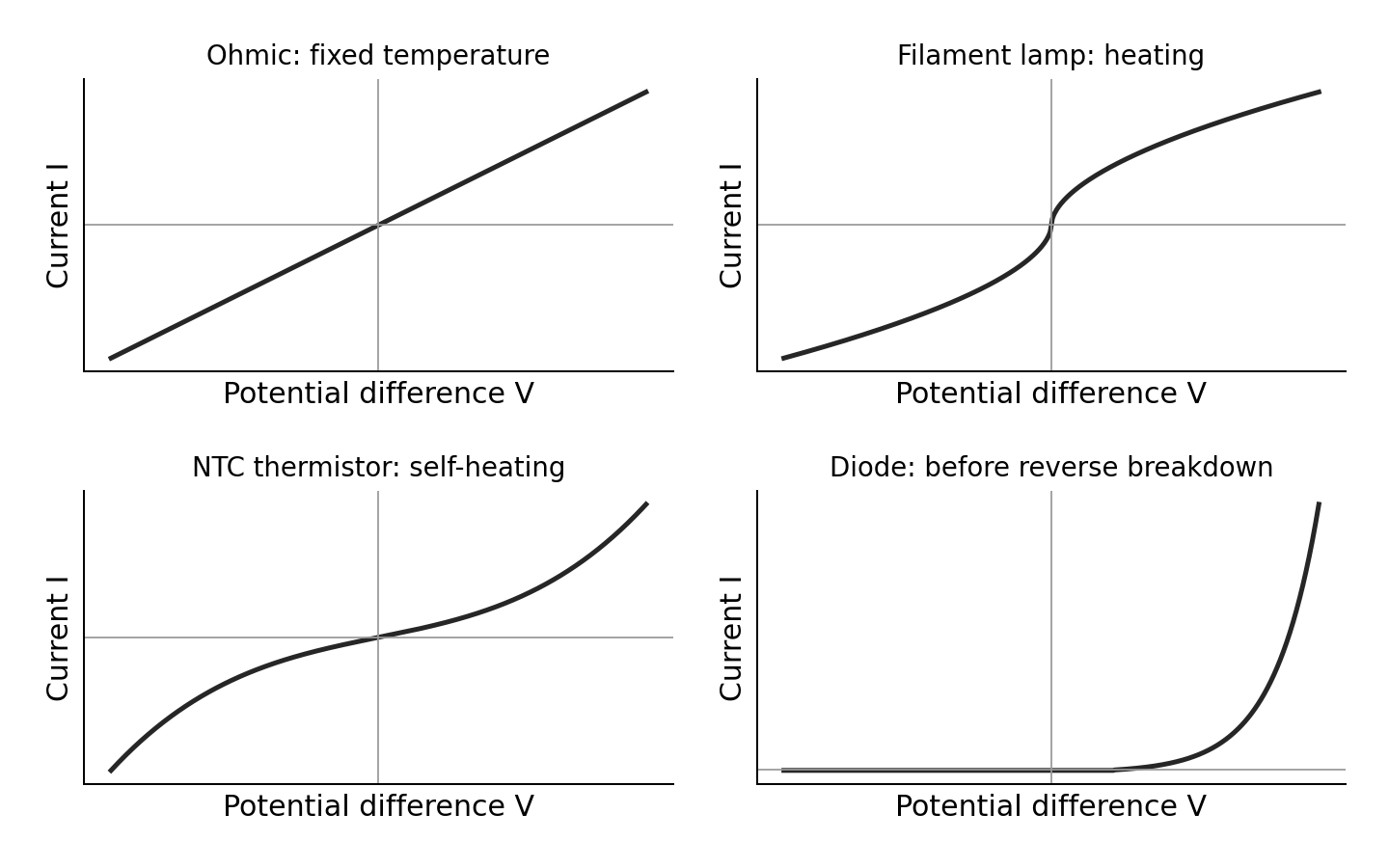
- Ohmic conductor at constant temperature: straight line through the origin. On an $I$-vertical, $V$-horizontal graph its gradient is $1/R$.
- Filament lamp: as voltage magnitude rises, heating increases resistance. The $I$–$V$ curve becomes less steep.
- NTC thermistor: heating lowers resistance. If current heats it sufficiently, the curve becomes steeper. At a controlled fixed temperature its behaviour over a suitable range can be approximately ohmic. Do not claim every thermistor curve must bend under every measurement condition.
- Diode: very small reverse current before breakdown; forward current rises rapidly after a characteristic knee. It conducts mainly in one direction. A real diode does not have one constant resistance.
For a curved graph, $R=V/I$ uses a line from the origin to the operating point. The tangent gradient is not generally $1/R$.
Resistivity and core practical 7
Resistivity 电阻率 $\rho$ is a material property at a stated temperature:
Lengthening a uniform wire increases resistance. Increasing cross-sectional area decreases it. Doubling diameter gives four times the area and one-quarter the resistance, if material, length and temperature stay unchanged.
For CP7, connect a uniform wire, ammeter, power supply, switch and current-limiting resistor in series. Connect a voltmeter across the measured wire length. Measure several lengths and find $R=V/I$ for each. Plot $R$ against $l$: gradient $=\rho/A$, so $\rho=A\times\text{gradient}$.
Measure diameter with a micrometer at several positions and orientations; check its zero. Measure length between the actual electrical contacts. Use a small current and switch off between readings to limit heating. Keep contacts secure. A non-zero intercept may indicate contact or lead resistance. Repeating readings reduces scatter but does not remove a diameter zero error. Because area depends on $d^2$, a small percentage diameter uncertainty contributes about twice that percentage to area uncertainty.
Worked example. A wire diameter is $0.40\ \text{mm}$. An $R$–$l$ graph has gradient $3.5\ \Omega\,\text{m}^{-1}$.
The charge-carrier model
The drift velocity 漂移速度 $v$ is the small mean directed velocity of charge carriers, not their random thermal speed:
Here $n$ is the number of mobile carriers per unit volume, $q$ is charge magnitude per carrier, and $A$ is cross-sectional area. A larger carrier density allows the same current with a smaller drift speed. In series wires the current is the same; changing $n$ or $A$ changes $v$.
Materials have different resistivities because their carrier densities and the ease of carrier motion differ. More scattering reduces drift speed for the same applied potential gradient. Carrier density alone does not explain every difference between materials.
Potential dividers, sensors and cells
Along a uniform wire carrying steady current at constant temperature, resistance grows in proportion to distance. The potential drop therefore grows in proportion to distance too. A potential–distance graph is straight. This assumes uniform material and area; a tapered or unevenly heated wire need not give a straight line.
A potential divider 分压器 uses series resistances to share a supply voltage:
The expression assumes the output is unloaded, or the attached load draws negligible current. If a load draws significant current, combine it in parallel with the output resistor first. Always identify which resistor the voltmeter spans.
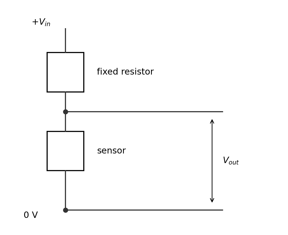
Worked example. A $6.0\ \text{V}$ supply feeds a $2.0\ \text{k}\Omega$ fixed resistor above an LDR. Find the output across the LDR when its resistance changes from $4.0$ to $1.0\ \text{k}\Omega$.
The output across this LDR falls when illumination rises. The output across the fixed resistor rises. Explain the named output, not just “the voltage changes”.
Explain sensors using carriers
In a metal, heating increases lattice vibrations. Conduction electrons scatter more often. The mobile electron number stays approximately constant, but drift speed at a given potential gradient decreases, so resistance rises.
In a negative-temperature-coefficient thermistor 负温度系数热敏电阻, heating releases more mobile carriers. The carrier-density increase dominates, so resistance falls. Avoid saying heating reduces lattice vibrations.
In a light-dependent resistor 光敏电阻 (LDR), absorbed light releases additional mobile carriers. Increased illumination raises carrier density and lowers resistance. It does not need to work by electrons leaving its surface.
For linked explanations, give the full chain: environmental change → carrier/scattering change → resistance change → divider fraction change → named output change. Keep the circuit arrangement in view throughout.
E.m.f., internal resistance and core practical 8
Electromotive force 电动势 $\mathcal{E}$ is energy supplied by the source per unit charge. It is measured in volts, despite its name. Internal resistance 内阻 $r$ causes energy transfer within the source when current flows. The terminal p.d. is the energy per coulomb available to the external circuit:
The source supplies power $\mathcal{E}I$, the external circuit receives $VI$, and internal heating is $I^2r$. These add consistently. With negligible current, terminal p.d. approaches e.m.f.
For CP8, connect a cell, ammeter, variable load and switch in series. Connect a high-resistance voltmeter across the cell terminals. Vary the external resistance and record pairs of $V$ and $I$. Plot $V$ vertically against $I$ horizontally. The best-fit line has intercept $\mathcal{E}$ and gradient $-r$. Take the magnitude of the gradient for $r$.
Use several settings and repeat. Open the switch between readings, avoid very small load resistance, and keep the cell temperature and charge state as steady as possible. Never short-circuit the cell. A graph that curves may show changing internal resistance or e.m.f.; do not force one fixed $r$ onto it without discussing the limitation.
Worked example. A cell graph passes through $(0.20\ \text{A},1.40\ \text{V})$ and $(0.60\ \text{A},1.20\ \text{V})$.
- Known: two points on the best-fit line. The gradient of $V=\mathcal{E}-Ir$ is $-r$.
$$r = -\frac{\Delta V}{\Delta I} = -\frac{1.20-1.40}{0.60-0.20}\ \Omega = 0.50\ \Omega$$$$\mathcal{E} = V+Ir = 1.40\ \text{V}+0.20\ \text{A}\times0.50\ \Omega = 1.50\ \text{V}$$
- Check using the second point: $1.20+0.60\times0.50=1.50\ \text{V}$ too. The terminal p.d. falls as current rises.
Check yourself
Use the matching exercise sheet after each section: 2.1 wave graphs; 2.2 standing waves; 2.3 refraction; 2.4 diffraction; 2.5 photons; 2.6 circuits; 2.7 dividers and cells.
Before using a past-paper set, check that you can:
- read an axis and identify whether it gives wavelength, period, pressure or displacement;
- explain a practical with apparatus, measurements, controlled variables, graph and precautions;
- distinguish phase from amplitude, and photon frequency from photon arrival rate;
- derive circuit combinations from charge and energy conservation;
- explain a sensor circuit as a connected causal chain;
- use an actual comparison to finish “deduce whether”, with units and a clear conclusion.
The reviewed January and June 2025 papers supply authentic examples, but do not test every requirement. Original practice fills the teaching gaps. Completing a sampled paper alone does not prove full syllabus coverage.